
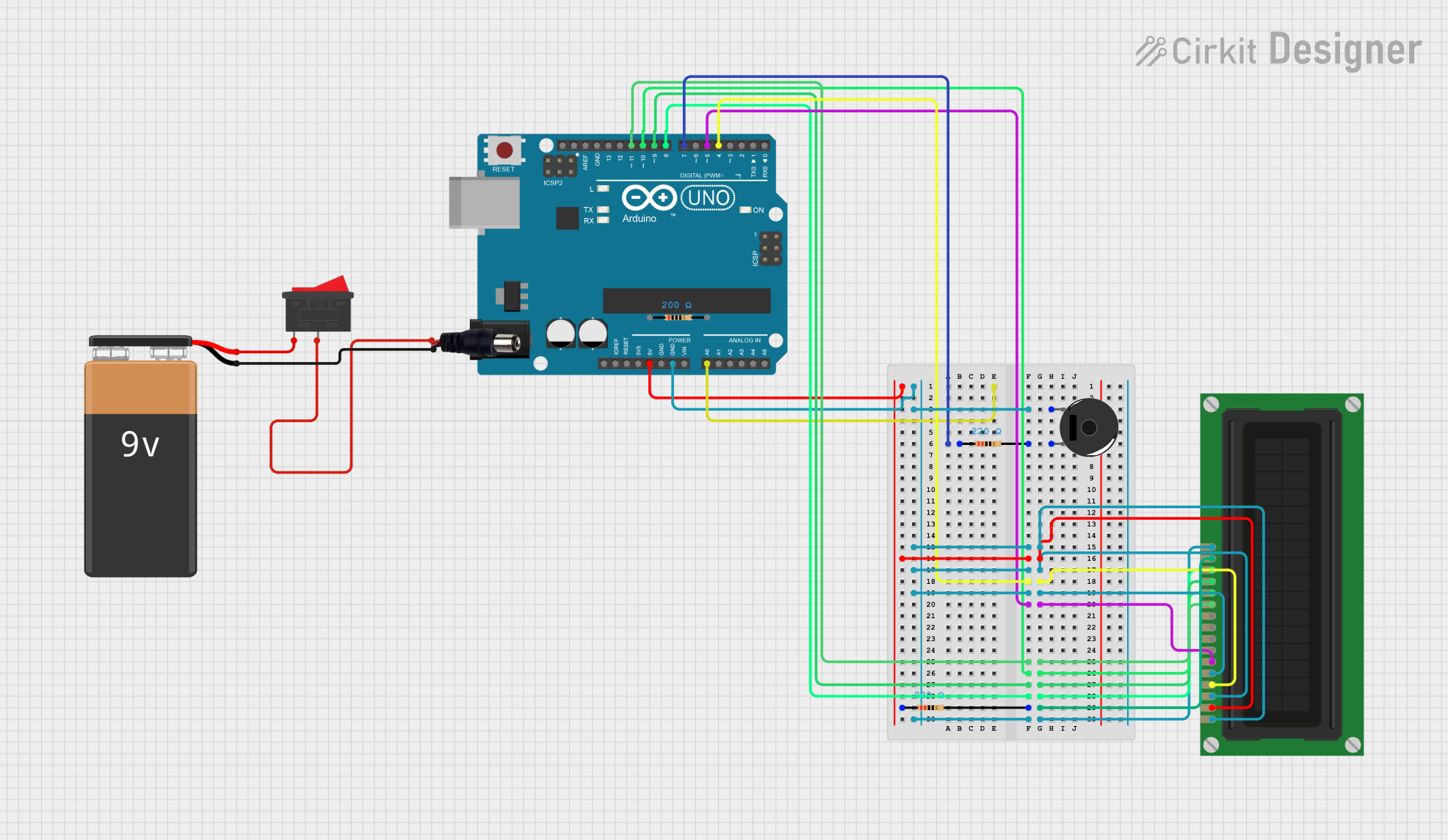
Circuit Documentation
Summary
This document provides a detailed overview of a circuit that includes an Arduino UNO, a 9V battery, resistors, a piezo buzzer, an LCD display, a rocker switch, and a power jack. The circuit is designed to interface the Arduino with the LCD display and piezo buzzer, powered by a 9V battery through a rocker switch and power jack.
Component List
Arduino UNO
- Description: A microcontroller board based on the ATmega328P.
- Pins: UNUSED, IOREF, Reset, 3.3V, 5V, GND, Vin, A0, A1, A2, A3, A4, A5, SCL, SDA, AREF, D13, D12, D11, D10, D9, D8, D7, D6, D5, D4, D3, D2, D1, D0
9V Battery
- Description: A standard 9V battery used to power the circuit.
- Pins: -, +
Resistor (200 Ohms)
- Description: A resistor with a resistance of 200 Ohms.
- Pins: pin1, pin2
Resistor (220 Ohms)
- Description: A resistor with a resistance of 220 Ohms.
- Pins: pin1, pin2
Piezo Buzzer
- Description: A piezoelectric buzzer used to produce sound.
- Pins: pin 1, pin 2
LCD Display (16 pin)
- Description: A 16-pin LCD display used to show information.
- Pins: VSS, VDD, VO, RS, R_W, E, DB0, DB1, DB2, DB3, DB4, DB5, DB6, DB7, A, K
Rocker Switch
- Description: A switch used to control the power supply.
- Pins: 1, 2
Power Jack
- Description: A power jack used to connect the 9V battery to the circuit.
- Pins: POSITIF, NEGATIF
Wiring Details
Arduino UNO
- A0: Not connected
- GND: Connected to:
- Piezo Buzzer (pin 1)
- LCD Display (VSS, VO, R_W, K)
- D7: Connected to Resistor (200 Ohms) pin1
- 5V: Connected to:
- LCD Display (VDD)
- Resistor (220 Ohms) pin1
- D4: Connected to LCD Display (RS)
- D5: Connected to LCD Display (E)
- D11: Connected to LCD Display (DB4)
- D10: Connected to LCD Display (DB5)
- D9: Connected to LCD Display (DB6)
- D8: Connected to LCD Display (DB7)
9V Battery
- -: Connected to Power Jack (NEGATIF)
- +: Connected to Rocker Switch (1)
Resistor (200 Ohms)
- pin1: Connected to Arduino UNO (D7)
- pin2: Connected to Piezo Buzzer (pin 2)
Resistor (220 Ohms)
- pin1: Connected to Arduino UNO (5V)
- pin2: Connected to LCD Display (A)
Piezo Buzzer
- pin 1: Connected to Arduino UNO (GND)
- pin 2: Connected to Resistor (200 Ohms) pin2
LCD Display (16 pin)
- VSS: Connected to Arduino UNO (GND)
- VDD: Connected to Resistor (220 Ohms) pin1
- VO: Connected to Arduino UNO (GND)
- RS: Connected to Arduino UNO (D4)
- R_W: Connected to Arduino UNO (GND)
- E: Connected to Arduino UNO (D5)
- DB4: Connected to Arduino UNO (D11)
- DB5: Connected to Arduino UNO (D10)
- DB6: Connected to Arduino UNO (D9)
- DB7: Connected to Arduino UNO (D8)
- A: Connected to Resistor (220 Ohms) pin2
- K: Connected to Arduino UNO (GND)
Rocker Switch
- 1: Connected to 9V Battery (+)
- 2: Connected to Power Jack (POSITIF)
Power Jack
- POSITIF: Connected to Rocker Switch (2)
- NEGATIF: Connected to 9V Battery (-)
Code Documentation
Arduino UNO Code
void setup() {
  // put your setup code here, to run once:

}

void loop() {
  // put your main code here, to run repeatedly:

}
This code is a basic template for the Arduino UNO. The setup() function is called once when the program starts and is used to initialize variables, pin modes, start using libraries, etc. The loop() function runs continuously after the setup() function has completed. This is where the main logic of the program is placed.