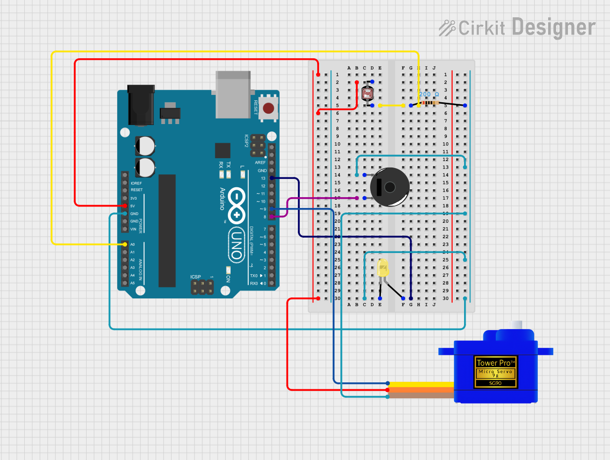
Arduino UNO Controlled Light-Sensing Servo with Alert Buzzer

Circuit Documentation
Summary
This circuit is designed to interact with environmental light using a photocell (LDR) to control a servomotor, an LED, and a piezo buzzer. The Arduino UNO serves as the central microcontroller unit, reading the LDR value and controlling the other components based on the light intensity detected. When the light level is below a certain threshold, the servomotor moves to a fixed position, the LED turns on, and the buzzer toggles between on and off states to create a beeping sound. The circuit includes a resistor to limit current to the buzzer and LED.
Component List
- Arduino UNO: A microcontroller board based on the ATmega328P. It has digital and analog I/O pins.
- Resistor (200 Ohms): A passive two-terminal electrical component that implements electrical resistance as a circuit element.
- LED (Yellow): A two-pin light-emitting diode that emits yellow light when powered.
- Servomotor SG90: A small and lightweight servo motor capable of precise control.
- Photocell (LDR): A light-dependent resistor whose resistance changes based on the light intensity.
- Piezo Buzzer: An electronic device that produces a tone when an electric signal is applied to it.
Wiring Details
Arduino UNO
- 5V: Connected to the VCC of the Servomotor SG90 and pin 1 of the Photocell (LDR).
- GND: Common ground connected to the GND of the Servomotor SG90, the cathode of the LED, and pin 2 of the Piezo Buzzer.
- A0: Connected to pin 0 of the Photocell (LDR) through a 200 Ohm resistor.
- D8: Connected to pin 1 of the Piezo Buzzer.
- D9: Connected to the SIG of the Servomotor SG90.
- D13: Connected to the anode of the LED.
Resistor (200 Ohms)
- Pin 1: Connected to pin 0 of the Photocell (LDR).
- Pin 2: Connected to the cathode of the LED and pin 1 of the Piezo Buzzer.
LED (Yellow)
- Cathode: Connected to pin 2 of the Resistor and the common ground.
- Anode: Connected to D13 on the Arduino UNO.
Servomotor SG90
- SIG: Connected to D9 on the Arduino UNO.
- VCC: Connected to 5V on the Arduino UNO.
- GND: Connected to the common ground.
Photocell (LDR)
- Pin 0: Connected to A0 on the Arduino UNO through a 200 Ohm resistor.
- Pin 1: Connected to 5V on the Arduino UNO.
Piezo Buzzer
- Pin 1: Connected to D8 on the Arduino UNO.
- Pin 2: Connected to the common ground through a 200 Ohm resistor.
Documented Code
#include <Servo.h>

Servo myServo;  // Create a servo object

int ldrPin = A0;   // LDR connected to analog pin A0
int ldrValue = 0;  // Variable to store LDR value
int servoPin = 9;  // Servo connected to pin 9
int ledPin = 13;   // LED connected to digital pin 13
int buzzerPin = 8; // Buzzer connected to digital pin 8
int threshold = 10;  // Set the light threshold
int fixedPosition = 100;  // Fixed position for the servo when it's dark

// Variables for buzzer beeping
unsigned long previousMillis = 0;
const long beepDuration = 500;  // Duration for the buzzer to be ON (in milliseconds)
const long silenceDuration = 500; // Duration for the buzzer to be OFF (in milliseconds)
bool buzzerState = false; // Buzzer state to track whether it should be ON or OFF
unsigned long lastChangeMillis = 0; // Time of last change of buzzer state

void setup() {
  myServo.attach(servoPin);  // Attach the servo to pin 9
  pinMode(ledPin, OUTPUT);    // Set the LED pin as an output
  pinMode(buzzerPin, OUTPUT); // Set the buzzer pin as an output
  Serial.begin(9600);         // Start serial communication for debugging
}

void loop() {
  ldrValue = analogRead(ldrPin);  // Read the LDR value (0-1023)

  // Check if the LDR value is above the threshold
  if (ldrValue > threshold) {
    // If light is detected (not dark):
    myServo.write(0);  // Move the servo to 0 degrees
    digitalWrite(ledPin, LOW);  // Turn the LED off
    noTone(buzzerPin);  // Turn the buzzer off
    buzzerState = false; // Reset buzzer state
    lastChangeMillis = 0; // Reset last change time
    Serial.print("LDR Value: ");
    Serial.print(ldrValue);
    Serial.println(" | Light Detected. Servo at 0 degrees. LED OFF. Buzzer OFF.");
  } else {
    // If the LDR value is below the threshold (dark):
    myServo.write(fixedPosition);  // Move the servo to the fixed position (180 degrees)
    digitalWrite(ledPin, HIGH);  // Turn the LED on

    unsigned long currentMillis = millis();

    // Check if it's time to change the buzzer state
    if (buzzerState) {
      // If buzzer is currently ON, check if it's time to turn it OFF
      if (currentMillis - lastChangeMillis >= beepDuration) {
        noTone(buzzerPin);  // Turn the buzzer off
        buzzerState = false; // Update state
        lastChangeMillis = currentMillis; // Record the time of change
      }
    } else {
      // If buzzer is currently OFF, check if it's time to turn it ON
      if (currentMillis - lastChangeMillis >= silenceDuration) {
        tone(buzzerPin, 1000);  // Turn the buzzer on with a 1000 Hz tone
        buzzerState = true; // Update state
        lastChangeMillis = currentMillis; // Record the time of change
      }
    }

    Serial.print("LDR Value: ");
    Serial.print(ldrValue);
    Serial.println(" | Below Threshold. Servo at 180 degrees. LED ON. Buzzer ON/OFF (Toggling).");
  }

  // No delay here to allow smooth operation
}
This code is designed to run on the Arduino UNO microcontroller. It initializes the connected components and controls them based on the LDR's readings. The servo's position, the LED's state, and the buzzer's beeping are all dependent on the light level detected by the LDR.