
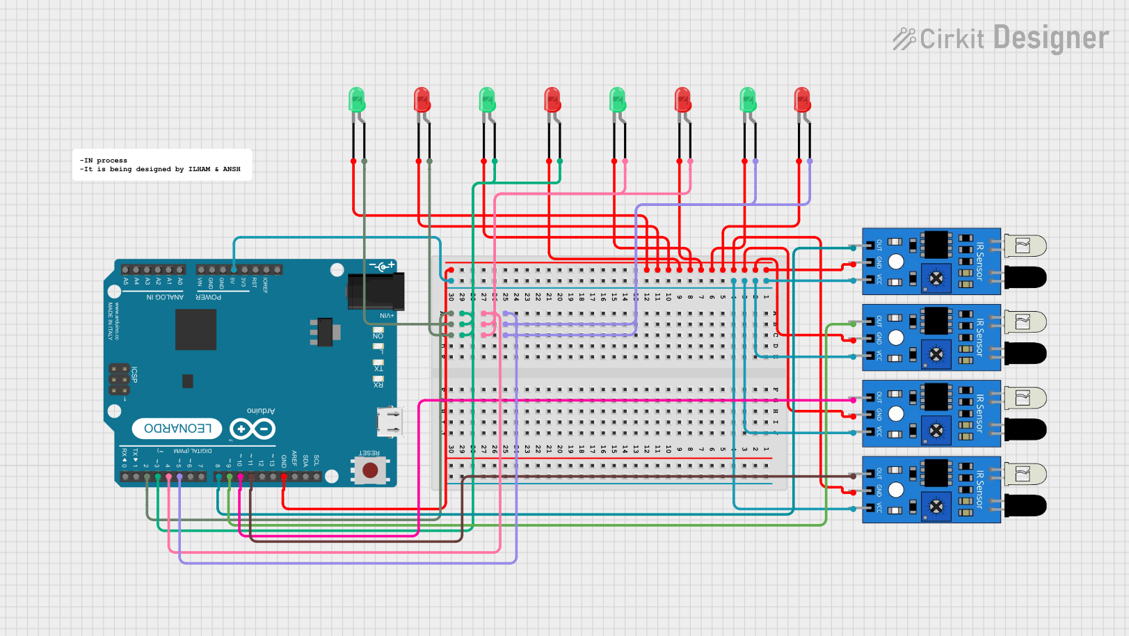
Circuit Documentation
Summary
This circuit is designed to control multiple LEDs based on the input from multiple IR sensors using an Arduino Leonardo (Rev3b). Each IR sensor is connected to a specific digital pin on the Arduino, and each LED is connected to another digital pin. When an IR sensor detects an object, the corresponding LED will light up.
Component List
Arduino Leonardo (Rev3b)
- Description: Microcontroller board based on the ATmega32u4.
- Pins: D0/RX, D1/TX, D2/SDA, D3 PWM/SCL, D4/A6, D5 PWM, D6 PWM/A7, D7, n.c., IOREF, RESET, 3V3, 5V, GND, VIN, A0, A1, A2, A3, A4, A5, D8/A8, D9 PWM/A9, D10 PWM/A10, D11 PWM, D12/A11, D13 PWM, AREF, SDA, SCL
IR Sensor
- Description: Infrared sensor for object detection.
- Pins: out, gnd, vcc
LED: Two Pin (red)
- Description: Red LED.
- Pins: cathode, anode
LED: Two Pin (green)
- Description: Green LED.
- Pins: cathode, anode
Wiring Details
Arduino Leonardo (Rev3b)
- D2/SDA: Connected to the anode of a green LED and the anode of a red LED.
- D3 PWM/SCL: Connected to the anode of a red LED and the anode of a green LED.
- D4/A6: Connected to the anode of a green LED and the anode of a red LED.
- D5 PWM: Connected to the anode of a green LED and the anode of a red LED.
- D8/A8: Connected to the output of an IR sensor.
- D9 PWM/A9: Connected to the output of an IR sensor.
- D10 PWM/A10: Connected to the output of an IR sensor.
- D11 PWM: Connected to the output of an IR sensor.
- 5V: Connected to the VCC of all IR sensors.
- GND: Connected to the GND of all IR sensors and the cathodes of all LEDs.
IR Sensor
- out: Connected to D8/A8 of the Arduino Leonardo.
- gnd: Connected to GND of the Arduino Leonardo.
- vcc: Connected to 5V of the Arduino Leonardo.
IR Sensor
- out: Connected to D9 PWM/A9 of the Arduino Leonardo.
- gnd: Connected to GND of the Arduino Leonardo.
- vcc: Connected to 5V of the Arduino Leonardo.
IR Sensor
- out: Connected to D10 PWM/A10 of the Arduino Leonardo.
- gnd: Connected to GND of the Arduino Leonardo.
- vcc: Connected to 5V of the Arduino Leonardo.
IR Sensor
- out: Connected to D11 PWM of the Arduino Leonardo.
- gnd: Connected to GND of the Arduino Leonardo.
- vcc: Connected to 5V of the Arduino Leonardo.
LED: Two Pin (red)
- anode: Connected to D2/SDA of the Arduino Leonardo.
- cathode: Connected to GND of the Arduino Leonardo.
LED: Two Pin (green)
- anode: Connected to D2/SDA of the Arduino Leonardo.
- cathode: Connected to GND of the Arduino Leonardo.
LED: Two Pin (red)
- anode: Connected to D3 PWM/SCL of the Arduino Leonardo.
- cathode: Connected to GND of the Arduino Leonardo.
LED: Two Pin (green)
- anode: Connected to D3 PWM/SCL of the Arduino Leonardo.
- cathode: Connected to GND of the Arduino Leonardo.
LED: Two Pin (red)
- anode: Connected to D4/A6 of the Arduino Leonardo.
- cathode: Connected to GND of the Arduino Leonardo.
LED: Two Pin (green)
- anode: Connected to D4/A6 of the Arduino Leonardo.
- cathode: Connected to GND of the Arduino Leonardo.
LED: Two Pin (red)
- anode: Connected to D5 PWM of the Arduino Leonardo.
- cathode: Connected to GND of the Arduino Leonardo.
LED: Two Pin (green)
- anode: Connected to D5 PWM of the Arduino Leonardo.
- cathode: Connected to GND of the Arduino Leonardo.
Code Documentation
/*
 * This Arduino sketch controls multiple LEDs based on the input from multiple
 * IR sensors. Each IR sensor is connected to a specific digital pin on the
 * Arduino Leonardo, and each LED is connected to another digital pin. When an
 * IR sensor detects an object, the corresponding LED will light up.
 */

// Define the pins for the LEDs
const int redLED1 = 2;     // Red LED 1 connected to D2
const int greenLED1 = 3;   // Green LED 1 connected to D3
const int redLED2 = 4;     // Red LED 2 connected to D4
const int greenLED2 = 5;   // Green LED 2 connected to D5
const int redLED3 = 6;     // Red LED 3 connected to D6
const int greenLED3 = 7;   // Green LED 3 connected to D7

// Define the pins for the IR sensor outputs
const int irSensor1 = 8;   // IR Sensor 1 connected to D8
const int irSensor2 = 9;   // IR Sensor 2 connected to D9
const int irSensor3 = 10;  // IR Sensor 3 connected to D10
const int irSensor4 = 11;  // IR Sensor 4 connected to D11

void setup() {
  // Initialize the LED pins as outputs
  pinMode(redLED1, OUTPUT);
  pinMode(greenLED1, OUTPUT);
  pinMode(redLED2, OUTPUT);
  pinMode(greenLED2, OUTPUT);
  pinMode(redLED3, OUTPUT);
  pinMode(greenLED3, OUTPUT);

  // Initialize the IR sensor pins as inputs
  pinMode(irSensor1, INPUT);
  pinMode(irSensor2, INPUT);
  pinMode(irSensor3, INPUT);
  pinMode(irSensor4, INPUT);

  // Turn off all LEDs initially
  digitalWrite(redLED1, LOW);
  digitalWrite(greenLED1, LOW);
  digitalWrite(redLED2, LOW);
  digitalWrite(greenLED2, LOW);
  digitalWrite(redLED3, LOW);
  digitalWrite(greenLED3, LOW);
}

void loop() {
  // Read the values from the IR sensors
  int sensorState1 = digitalRead(irSensor1);
  int sensorState2 = digitalRead(irSensor2);
  int sensorState3 = digitalRead(irSensor3);
  int sensorState4 = digitalRead(irSensor4);

  // Control LEDs based on IR sensor states
  digitalWrite(redLED1, sensorState1 == LOW ? HIGH : LOW);
  digitalWrite(greenLED1, sensorState1 == LOW ? HIGH : LOW);
  digitalWrite(redLED2, sensorState2 == LOW ? HIGH : LOW);
  digitalWrite(greenLED2, sensorState2 == LOW ? HIGH : LOW);
  digitalWrite(redLED3, sensorState3 == LOW ? HIGH : LOW);
  digitalWrite(greenLED3, sensorState3 == LOW ? HIGH : LOW);

  // Small delay to debounce the sensor input
  delay(100);
}
This code initializes the pins for the LEDs and IR sensors, sets the initial state of the LEDs to off, and continuously reads the state of the IR sensors to control the LEDs accordingly.