
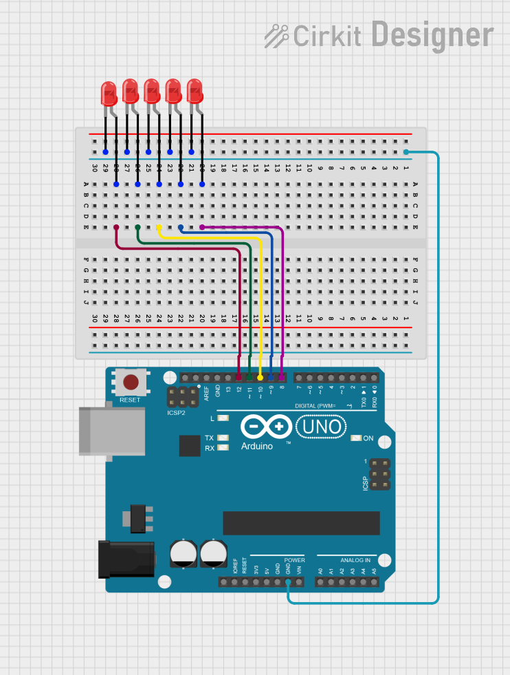
Circuit Documentation
Summary of the Circuit
This circuit consists of an Arduino UNO microcontroller board connected to a series of six red two-pin LEDs. The Arduino UNO is used to control the state of each LED, allowing them to be turned on or off individually. The common ground (GND) of the Arduino is connected to the cathodes of all LEDs, while individual digital pins on the Arduino are connected to the anodes of each LED, allowing for independent control.
Component List
Arduino UNO
- Description: A microcontroller board based on the ATmega328P.
- Purpose: Acts as the central controller for the circuit, driving the LEDs.
- Pins Used: GND, D8, D9, D10, D11, D12.
LED: Two Pin (red)
- Description: A basic red light-emitting diode.
- Purpose: Emits light when powered.
- Pins Used: Anode, Cathode.
Wiring Details
Arduino UNO
- GND: Connected to the cathodes of all LEDs.
- D12: Connected to the anode of the first LED.
- D11: Connected to the anode of the second LED.
- D10: Connected to the anode of the third LED.
- D9: Connected to the anode of the fourth LED.
- D8: Connected to the anode of the fifth LED.
LED: Two Pin (red)
- Cathode: Connected to the GND of the Arduino UNO.
- Anode: Connected to a digital pin (D8-D12) on the Arduino UNO for individual control.
Documented Code
Arduino UNO - sketch.ino
void setup() {
  // put your setup code here, to run once:

}

void loop() {
  // put your main code here, to run repeatedly:

}
Arduino UNO - documentation.txt
(No additional documentation provided)
This concludes the documentation for the given circuit. The code provided is a template and does not include the logic for controlling the LEDs. To complete the circuit functionality, the setup() function should be modified to initialize the digital pins connected to the LEDs as outputs, and the loop() function should contain the logic to turn the LEDs on or off.