Cirkit Designer
Your all-in-one circuit design IDE
Home /
Project Documentation
Arduino-Based Automatic Rain-Sensing Rooftop with LCD Display
Circuit Documentation
Summary
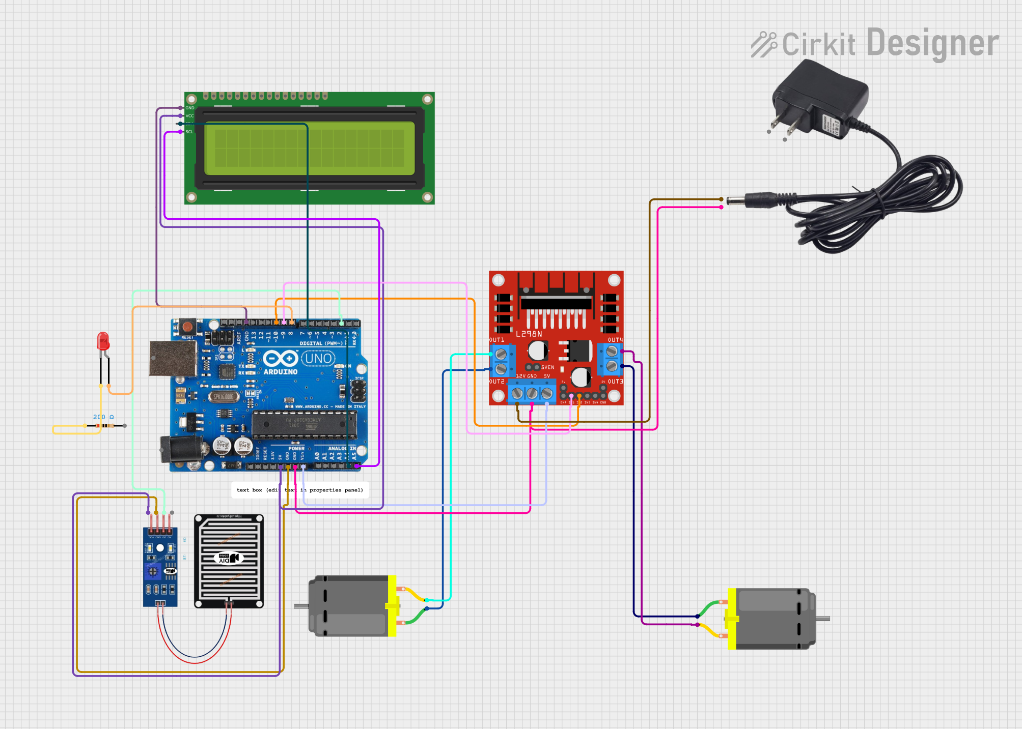
This circuit is designed to automatically control a rooftop based on rain detection. It uses an Arduino Uno R3 to read input from a rain sensor and control two DC motors via an L298N motor driver. The status of the rooftop (open or closed) is displayed on a 16x2 I2C LCD. Additionally, an LED is used to indicate the status of the system.
Component List
L298N DC Motor Driver
- Description: Motor driver module used to control the direction and speed of DC motors.
- Pins: OUT1, OUT2, 12V, GND, 5V, OUT3, OUT4, 5V-ENA-JMP-I, 5V-ENA-JMP-O, +5V-J1, +5V-J2, ENA, IN1, IN2, IN3, IN4, ENB
DC Motor
- Description: Standard DC motor.
- Pins: pin 1, pin 2
12V Adapter
- Description: Power supply adapter providing 12V.
- Pins: VCC, GND
Arduino Uno R3
- Description: Microcontroller board based on the ATmega328P.
- Pins: D8, D9, D10, D11, D12, D13, GND, AREF, SDA, SCL, D0/RX, D1/Tx, D2, D3, D4, D5, 6, D7, A5/SCL, A4/SDA, A3, A2, A1, A0, Vin, 5V, 3.3V, RESET, IOREF, NONE, USB Jack, Power Jack
Resistor
- Description: Resistor with a resistance of 200 Ohms.
- Pins: pin1, pin2
LED: Two Pin (red)
- Description: Red LED.
- Pins: cathode, anode
16x2 I2C LCD
- Description: LCD display with I2C interface.
- Pins: GND, VCC, SDA, SCL
RAIN SENSOR
- Description: Sensor to detect rain.
- Pins: AO, DO, GRD, VCC
Wiring Details
L298N DC Motor Driver
- OUT1 connected to pin 2 of DC Motor 1
- OUT2 connected to pin 1 of DC Motor 1
- OUT3 connected to pin 1 of DC Motor 2
- OUT4 connected to pin 2 of DC Motor 2
- 12V connected to VCC of 12V Adapter
- GND connected to GND of 12V Adapter and GND of Arduino Uno R3
- 5V connected to Vin of Arduino Uno R3
- IN1 connected to D9 of Arduino Uno R3
- IN2 connected to D10 of Arduino Uno R3
DC Motor 1
- pin 1 connected to OUT2 of L298N DC Motor Driver
- pin 2 connected to OUT1 of L298N DC Motor Driver
DC Motor 2
- pin 1 connected to OUT3 of L298N DC Motor Driver
- pin 2 connected to OUT4 of L298N DC Motor Driver
12V Adapter
- VCC connected to 12V of L298N DC Motor Driver
- GND connected to GND of L298N DC Motor Driver and GND of Arduino Uno R3
Arduino Uno R3
- D2 connected to DO of RAIN SENSOR
- GND connected to GRD of RAIN SENSOR and GND of 16x2 I2C LCD
- 5V connected to VCC of RAIN SENSOR and VCC of 16x2 I2C LCD
- Vin connected to 5V of L298N DC Motor Driver
- D9 connected to IN1 of L298N DC Motor Driver
- D10 connected to IN2 of L298N DC Motor Driver
- D8 connected to anode of LED: Two Pin (red)
- A5/SCL connected to SCL of 16x2 I2C LCD
- A4/SDA connected to SDA of 16x2 I2C LCD
Resistor
- pin1 connected to cathode of LED: Two Pin (red)
LED: Two Pin (red)
- anode connected to D8 of Arduino Uno R3
- cathode connected to pin1 of Resistor
16x2 I2C LCD
- GND connected to GND of Arduino Uno R3
- VCC connected to 5V of Arduino Uno R3
- SDA connected to A4/SDA of Arduino Uno R3
- SCL connected to A5/SCL of Arduino Uno R3
RAIN SENSOR
- DO connected to D2 of Arduino Uno R3
- GRD connected to GND of Arduino Uno R3
- VCC connected to 5V of Arduino Uno R3
Documented Code
Arduino Uno R3 Code
// Define pins
const int rainSensorPin = 2;  // Digital pin connected to rain sensor
const int motorPin1 = 9;      // Motor driver input pin 1
const int motorPin2 = 10;     // Motor driver input pin 2

// Define states
bool isRoofClosed = false;

void setup() {
  // Initialize pins
  pinMode(rainSensorPin, INPUT);
  pinMode(motorPin1, OUTPUT);
  pinMode(motorPin2, OUTPUT);

  // Start with the roof open
  openRoof();

  Serial.begin(9600);  // Initialize serial communication for debugging
}

void loop() {
  int rainDetected = digitalRead(rainSensorPin);

  if (rainDetected == LOW && !isRoofClosed) {
    // Rain detected, close the roof
    closeRoof();
  } else if (rainDetected == HIGH && isRoofClosed) {
    // No rain, open the roof
    openRoof();
  }

  delay(1000);  // Check every second
}

void closeRoof() {
  Serial.println("Closing Roof...");
  // Rotate motor to close the roof
  digitalWrite(motorPin1, HIGH);
  digitalWrite(motorPin2, LOW);

  // Assuming it takes 5 seconds to close the roof
  delay(5000);

  // Stop the motor
  stopMotor();

  isRoofClosed = true;
}

void openRoof() {
  Serial.println("Opening Roof...");
  // Rotate motor to open the roof
  digitalWrite(motorPin1, LOW);
  digitalWrite(motorPin2, HIGH);

  // Assuming it takes 5 seconds to open the roof
  delay(5000);

  // Stop the motor
  stopMotor();

  isRoofClosed = false;
}

void stopMotor() {
  // Stop the motor by setting both inputs to LOW
  digitalWrite(motorPin1, LOW);
  digitalWrite(motorPin2, LOW);
}
16x2 I2C LCD Code
/*
 * Automatic Rooftop Sensor
 * This code interfaces with a 16x2 I2C LCD to display the status of the
 * rooftop (open or closed) based on the rain sensor input.
 */

#include <Wire.h>
#include <LiquidCrystal_I2C.h>

// Initialize the LCD, set the LCD address to 0x27 for a 16 chars and 2 line display
LiquidCrystal_I2C lcd(0x27, 16, 2);

void setup() {
  // Initialize the LCD
  lcd.begin();
  lcd.backlight();
  lcd.setCursor(0, 0);
  lcd.print("Rooftop Status:");
}

void loop() {
  // Read the rain sensor status from the Arduino Uno
  int rainDetected = digitalRead(2); // Assuming rain sensor is connected to pin D2

  lcd.setCursor(0, 1);
  if (rainDetected == LOW) {
    lcd.print("Closing Roof   ");
  } else {
    lcd.print("Opening Roof   ");
  }

  delay(1000); // Update the display every second
}
DC Motor Code
void setup() {
  // put your setup code here, to run once:

}

void loop() {
  // put your main code here, to