Cirkit Designer
Your all-in-one circuit design IDE
Home /
Project Documentation
Arduino Uno R3 Controlled Bluetooth Robot with L298N Motor Driver and LED Indicator
Circuit Documentation
Summary
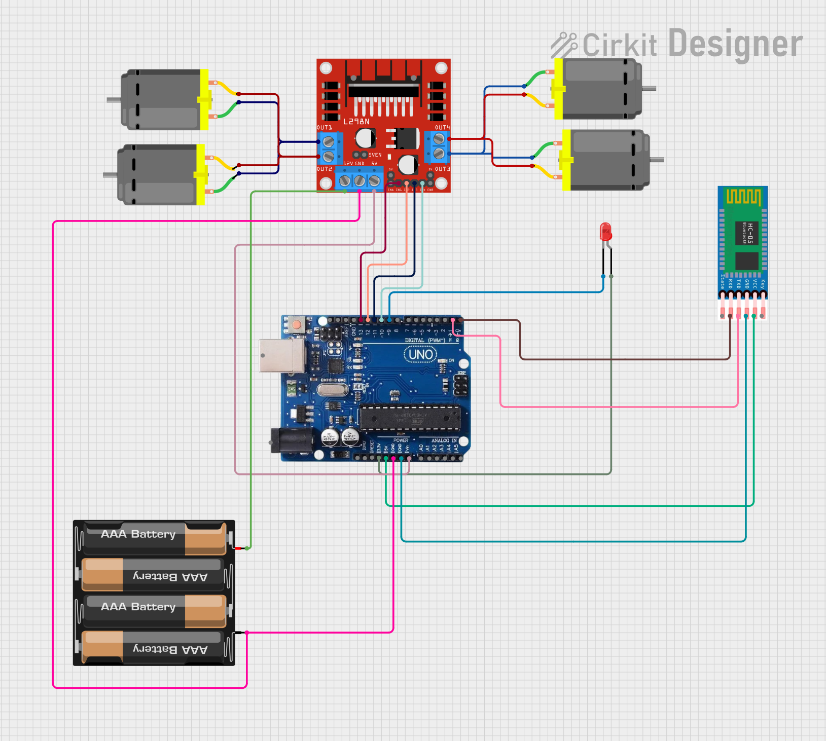
This circuit is designed to control a set of DC motors using an Arduino Uno R3 microcontroller and an L298N DC motor driver. The circuit also includes an HC-05 Bluetooth module for wireless communication and a red LED as an indicator. Power is supplied by a 4 x AAA battery mount. The Arduino Uno R3 is programmed to interpret serial commands to control the motion of the motors (forward, reverse, left, right, stop) and to toggle the LED on or off.
Component List
Arduino Uno R3
- Microcontroller board based on the ATmega328P
- It has 14 digital input/output pins, 6 analog inputs, a USB connection, a power jack, an ICSP header, and a reset button.
L298N DC Motor Driver
- A dual H-bridge motor driver that can drive two DC motors or one stepper motor.
- It has pins for motor outputs, power supply, and control inputs.
DC Motor (4 units)
- A standard DC motor used for creating rotational motion.
- Each motor has two pins for power connection.
HC-05 Bluetooth Module
- A wireless communication module that allows for serial communication via Bluetooth.
- It has pins for enabling, power supply, ground, and serial communication (TX/RX).
LED: Two Pin (red)
- A basic red LED used as an indicator.
- It has an anode and a cathode pin for power connection.
4 x AAA Battery Mount
- A battery holder for four AAA batteries to provide power to the circuit.
- It has positive and negative terminals for power output.
Wiring Details
Arduino Uno R3
3.3Vconnected to the anode of the red LED.5Vconnected to the VCC of the HC-05 Bluetooth module.GNDconnected to the ground of the L298N motor driver, HC-05 Bluetooth module, and the negative terminal of the battery mount.VINconnected to the 5V input of the L298N motor driver.- Digital pins
13,12,11, and10connected to theIN1,IN2,IN3, andIN4of the L298N motor driver respectively. - Digital pin
9connected to the cathode of the red LED. - Digital pins
1and0(TX/RX) connected to the RXD and TXD of the HC-05 Bluetooth module respectively.
L298N DC Motor Driver
OUT1andOUT2connected to the first pair of DC motors.OUT3andOUT4connected to the second pair of DC motors.12Vconnected to the positive terminal of the battery mount.GNDconnected to the ground of the Arduino Uno R3 and the negative terminal of the battery mount.5Vconnected to the VIN of the Arduino Uno R3.IN1,IN2,IN3, andIN4connected to the digital pins13,12,11, and10of the Arduino Uno R3 respectively.
DC Motors
- Each motor has two pins connected to the corresponding output pins of the L298N motor driver.
HC-05 Bluetooth Module
VCCconnected to the 5V of the Arduino Uno R3.GNDconnected to the ground of the Arduino Uno R3.TXDconnected to the RX (pin0) of the Arduino Uno R3.RXDconnected to the TX (pin1) of the Arduino Uno R3.
LED: Two Pin (red)
Anodeconnected to the3.3Vof the Arduino Uno R3.Cathodeconnected to the digital pin9of the Arduino Uno R3.
4 x AAA Battery Mount
+connected to the12Vof the L298N motor driver.-connected to the ground of the L298N motor driver and the Arduino Uno R3.
Documented Code
char t;

void setup() {
  pinMode(13, OUTPUT);   // Left motors forward
  pinMode(12, OUTPUT);   // Left motors reverse
  pinMode(11, OUTPUT);   // Right motors forward
  pinMode(10, OUTPUT);   // Right motors reverse
  pinMode(9, OUTPUT);    // LED
  Serial.begin(9600);
}

void loop() {
  if (Serial.available()) {
    t = Serial.read();
    Serial.println(t);
  }

  if (t == 'F') {            // Move forward (all motors rotate in forward direction)
    digitalWrite(13, HIGH);
    digitalWrite(11, HIGH);
  } else if (t == 'B') {     // Move reverse (all motors rotate in reverse direction)
    digitalWrite(12, HIGH);
    digitalWrite(10, HIGH);
  } else if (t == 'L') {     // Turn right (left side motors rotate in forward direction, right side motors don't rotate)
    digitalWrite(11, HIGH);
  } else if (t == 'R') {     // Turn left (right side motors rotate in forward direction, left side motors don't rotate)
    digitalWrite(13, HIGH);
  } else if (t == 'W') {     // Turn LED on
    digitalWrite(9, HIGH);
  } else if (t == 'w') {     // Turn LED off
    digitalWrite(9, LOW);
  } else if (t == 'S') {     // STOP (all motors stop)
    digitalWrite(13, LOW);
    digitalWrite(12, LOW);
    digitalWrite(11, LOW);
    digitalWrite(10, LOW);
  }
  delay(100);
}
This code is designed to run on the Arduino Uno R3. It sets up the digital pins connected to the motor driver and LED as outputs and initializes serial communication. The loop function reads a character from the serial port and controls the motors and LED based on the received command.