
Raspberry Pi and MCP3008 Controlled Robotic Hand with Muscle Sensor Integration
View and Edit Project In Cirkit Designer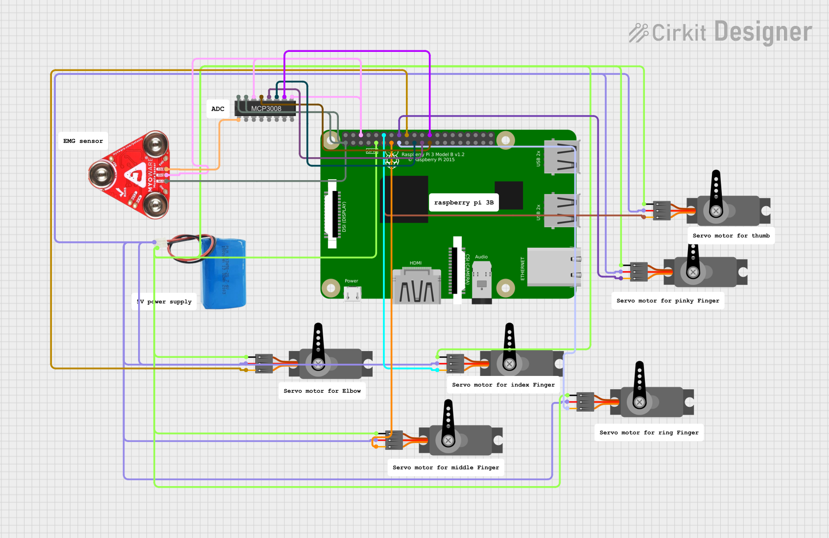
Circuit Documentation
Summary
This circuit is designed to read muscle signals using a Myoware 2.0 Muscle Sensor and convert them to electrical signals using an MCP3008 8-channel 10-bit ADC. The converted signals are then sent to a Raspberry Pi 3B for further processing. Additionally, the circuit controls multiple servo motors to simulate hand and finger movements based on predefined angles.
Component List
MCP3008 8-channel 10-bit ADC
- Description: Analog-to-digital converter
- Pins: Not specified
Servo
- Description: Actuator for simulating movements
- Pins: GND, VCC, PWM
Comment
- Description: Placeholder for comments
- Pins: None
5V Battery
- Description: Power supply
- Pins: Positive, Negative
Raspberry Pi 3B
- Description: Microcontroller for processing signals
- Pins: 3v3, GPIO2, GPIO3, GPIO4, GND, GPIO17, GPIO27, GPIO22, 3V3, GPIO10, GPIO9, GPIO11, ID_SD, GPIO5, GPIO6, GPIO13, GPIO19, GPIO26, GPIO21, GPIO20, GPIO16, GPIO12, ID_SC, GPIO7, GPIO8, GPIO25, GPIO24, GPIO23, GPIO18, GPIO15, GPIO14, 5V
Myoware 2.0 Muscle Sensor
- Description: Sensor for detecting muscle signals
- Pins: VIN, GND, ENV
Wiring Details
MCP3008 8-channel 10-bit ADC
- Pin (Not specified) connected to Myoware 2.0 Muscle Sensor ENV
- Pin (Not specified) connected to Raspberry Pi 3B 3v3
- Pin (Not specified) connected to Myoware 2.0 Muscle Sensor VIN
- Pin (Not specified) connected to Raspberry Pi 3B GND
- Pin (Not specified) connected to Myoware 2.0 Muscle Sensor GND
- Pin (Not specified) connected to Raspberry Pi 3B GPIO11
- Pin (Not specified) connected to Raspberry Pi 3B GPIO9
- Pin (Not specified) connected to Raspberry Pi 3B GPIO10
- Pin (Not specified) connected to Raspberry Pi 3B GPIO8
Servo
- GND connected to Raspberry Pi 3B GND
- GND connected to 5V Battery Negative
- VCC connected to 5V Battery Positive
- PWM connected to Raspberry Pi 3B GPIO24 (Hand Movement Control)
- PWM connected to Raspberry Pi 3B GPIO18 (Finger Movement Control)
- PWM connected to Raspberry Pi 3B GPIO17 (Finger Movement Control)
- PWM connected to Raspberry Pi 3B GPIO22 (Finger Movement Control)
- PWM connected to Raspberry Pi 3B GPIO27 (Finger Movement Control)
- PWM connected to Raspberry Pi 3B GPIO23 (Finger Movement Control)
5V Battery
- Positive connected to Servo VCC
- Negative connected to Servo GND
Raspberry Pi 3B
- 3v3 connected to MCP3008 8-channel 10-bit ADC
- GND connected to MCP3008 8-channel 10-bit ADC
- GND connected to Myoware 2.0 Muscle Sensor GND
- GND connected to Servo GND
- GPIO11 connected to MCP3008 8-channel 10-bit ADC
- GPIO9 connected to MCP3008 8-channel 10-bit ADC
- GPIO10 connected to MCP3008 8-channel 10-bit ADC
- GPIO8 connected to MCP3008 8-channel 10-bit ADC
- GPIO24 connected to Servo PWM (Hand Movement Control)
- GPIO18 connected to Servo PWM (Finger Movement Control)
- GPIO17 connected to Servo PWM (Finger Movement Control)
- GPIO22 connected to Servo PWM (Finger Movement Control)
- GPIO27 connected to Servo PWM (Finger Movement Control)
- GPIO23 connected to Servo PWM (Finger Movement Control)
Myoware 2.0 Muscle Sensor
- VIN connected to MCP3008 8-channel 10-bit ADC
- GND connected to MCP3008 8-channel 10-bit ADC
- ENV connected to MCP3008 8-channel 10-bit ADC
Documented Code
MCP3008 8-channel 10-bit ADC Code
/*
 * Muscle Signal to Electrical Signal Converter
 * This Arduino sketch reads muscle signals from a GSR sensor via an MCP3008 ADC
 * and sends the converted electrical signal to the Raspberry Pi 5 for further
 * processing.
 */

#include <SPI.h>

// Pin definitions
const int GSR_SENSOR_PIN = 0; // MCP3008 channel 0
const int CS_PIN = 10; // Chip Select pin for SPI

void setup() {
  // Initialize SPI
  SPI.begin();
  pinMode(CS_PIN, OUTPUT);
  digitalWrite(CS_PIN, HIGH);
  // Initialize serial communication
  Serial.begin(9600);
}

int readADC(int channel) {
  // Start SPI transaction
  SPI.beginTransaction(SPISettings(14000000, MSBFIRST, SPI_MODE0));
  digitalWrite(CS_PIN, LOW);
  // Send start bit, single-ended bit, and channel number
  byte command = 0b11000000 | ((channel & 0b111) << 3);
  SPI.transfer(command);
  // Read high and low bytes
  byte highByte = SPI.transfer(0x00);
  byte lowByte = SPI.transfer(0x00);
  digitalWrite(CS_PIN, HIGH);
  SPI.endTransaction();
  // Combine bytes into a 10-bit value
  int value = ((highByte & 0x03) << 8) | lowByte;
  return value;
}

void loop() {
  // Read muscle signal from GSR sensor
  int muscleSignal = readADC(GSR_SENSOR_PIN);
  // Send the signal to Raspberry Pi via serial
  Serial.println(muscleSignal);
  // Small delay to prevent overwhelming the serial buffer
  delay(50);
}
Servo Code (Hand Movement Control)
/*
 * Hand Movement Control
 * This Arduino sketch controls a servo motor to simulate hand movements.
 * The servo motor is connected to the microcontroller and receives PWM
 * signals to adjust its position.
 */

#include <Servo.h>

// Pin definitions
const int SERVO_PIN = 9; // PWM pin for the servo motor

// Servo object
Servo handServo;

void setup() {
  // Attach the servo to the specified pin
  handServo.attach(SERVO_PIN);
}

void loop() {
  // Move the servo to 0 degrees
  handServo.write(0);
  delay(1000); // Wait for 1 second
  // Move the servo to 90 degrees
  handServo.write(90);
  delay(1000); // Wait for 1 second
  // Move the servo to 180 degrees
  handServo.write(180);
  delay(1000); // Wait for 1 second
}
Servo Code (Finger Movement Control)
/*
 * Finger Movement Control
 * This Arduino sketch controls a servo motor to simulate finger movements.
 * The servo motor is connected to the microcontroller and receives PWM
 * signals to adjust its position based on predefined angles.
 */

#include <Servo.h>

// Pin definitions
const int SERVO_PIN = 9; // PWM pin for the servo motor

// Servo object
Servo fingerServo;

void setup() {
  // Attach the servo to the specified pin
  fingerServo.attach(SERVO_PIN);
}

void loop() {
  // Move the servo to 0 degrees
  fingerServo.write(0);
  delay(1000); // Wait for 1 second
  // Move the servo to 45 degrees
  fingerServo.write(45);
  delay(1000); // Wait for 1 second
  // Move the servo to 90 degrees
  fingerServo.write(90);
  delay(1000); // Wait for 1 second
  // Move the servo to 135 degrees
  fingerServo.write(135);
  delay(1000); // Wait for 1 second
  // Move the servo to 180 degrees
  fingerServo.write(180);
  delay(1000); // Wait for 1 second
}
This documentation provides a comprehensive overview of the circuit, including a summary, component list, wiring details, and documented code for each microcontroller.