Cirkit Designer
Your all-in-one circuit design IDE
Home /
Project Documentation
Arduino-Controlled IR Relay Switching System

Circuit Documentation
Summary
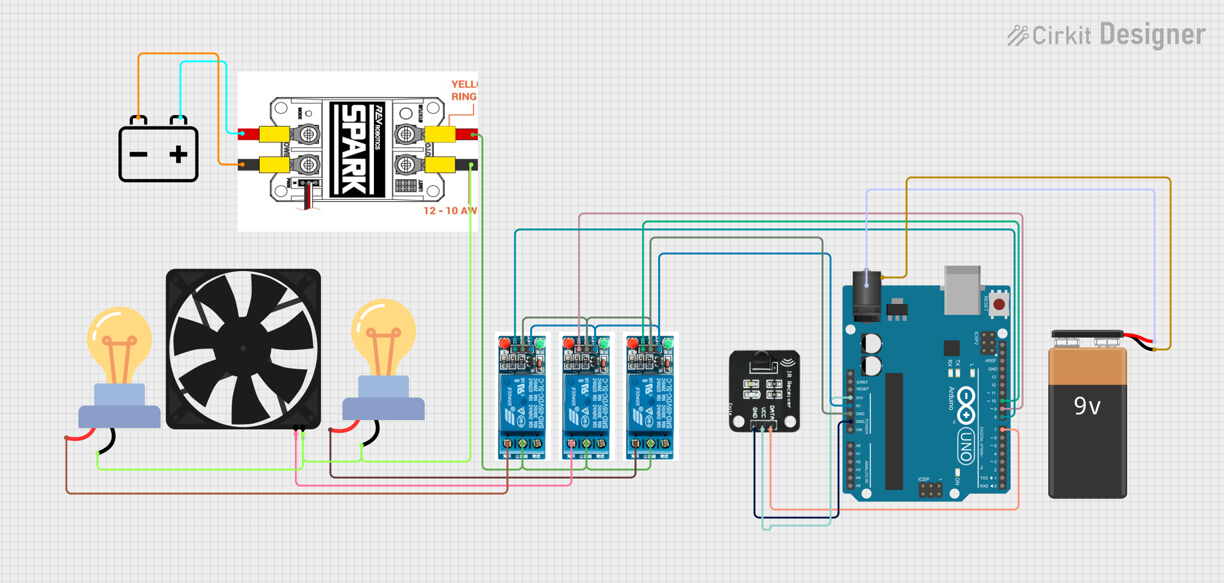
This circuit integrates an Arduino UNO microcontroller with multiple peripherals including IR Receiver, 5V relays, LED bulbs, a fan, a Spark motor driver, and power sources like a 12V battery, a 9V battery, and a 2.1mm DC Barrel Jack. The Arduino UNO controls the relays which in turn switch various loads such as LED bulbs and a fan. The IR Receiver is used to receive signals, presumably for remote control functionality. The Spark motor driver is connected to a 12V battery and is likely used to control a motor.
Component List
Arduino UNO
- Microcontroller board based on the ATmega328P
- It has 14 digital input/output pins, 6 analog inputs, a 16 MHz quartz crystal, a USB connection, a power jack, an ICSP header, and a reset button.
5V Relay (x3)
- An electromechanical switch that allows a low-power circuit to switch a relatively high current on and off.
- It has a Normally Open (NO) contact, a Common terminal (COM), a Normally Closed (NC) contact, an input signal pin (In), a ground pin (GND), and a power supply pin (VCC).
IR Receiver
- A component that receives IR signals from a remote control.
- It has a data output pin (DATA), a power supply pin (VCC), and a ground pin (GND).
LED Bulb AC (x2)
- An AC-powered light-emitting diode bulb.
- It has a positive (+) and a negative (-) terminal.
Fan
- A small DC fan for cooling purposes.
- It has a ground (GND) and a power supply pin (5V).
Spark Motor Driver
- A motor driver capable of driving a bidirectional DC motor.
- It has pins for motor power supply (V+, V-), logic power supply (VCC), ground (GND), pulse-width modulation input (PWM), and motor outputs (M+, M-).
12V Battery
- A DC power source providing 12 volts.
- It has a positive (+) and a negative (-) terminal.
9V Battery
- A DC power source providing 9 volts.
- It has a positive (+) and a negative (-) terminal.
2.1mm DC Barrel Jack
- A power connector typically used for attaching external power sources to the circuit.
- It has a switch pin (switch), a sleeve pin (sleeve), and a center pin (center).
Wiring Details
Arduino UNO
3.3Vconnected to IR Receiver VCC5Vconnected to all 5V relay VCC pinsGNDconnected to all 5V relay GND pins and IR Receiver GNDD10connected to 5V relay (instance 1) InD9connected to 5V relay (instance 2) InD8connected to 5V relay (instance 3) InD7connected to IR Receiver DATA
5V Relay (instance 1)
Normally Openconnected to LED bulb AC (instance 1) +Common terminalinterconnected with other relays and Spark M+
5V Relay (instance 2)
Normally Openconnected to Fan 5V
5V Relay (instance 3)
Normally Openconnected to LED bulb AC (instance 2) +
IR Receiver
DATAconnected to Arduino UNO D7VCCconnected to Arduino UNO 3.3VGNDconnected to Arduino UNO GND
LED Bulb AC (instance 1)
+connected to 5V relay (instance 1) Normally Open-interconnected with other AC loads and Spark M-
LED Bulb AC (instance 2)
+connected to 5V relay (instance 3) Normally Open-interconnected with other AC loads and Spark M-
Fan
5Vconnected to 5V relay (instance 2) Normally OpenGNDinterconnected with other AC loads and Spark M-
Spark Motor Driver
M+interconnected with relay Common terminalsM-interconnected with other AC loadsV+connected to 12V Battery +V-connected to 12V Battery -
12V Battery
+connected to Spark V+-connected to Spark V-
9V Battery
+connected to 2.1mm DC Barrel Jack switch-connected to 2.1mm DC Barrel Jack sleeve
2.1mm DC Barrel Jack
switchconnected to 9V Battery +sleeveconnected to 9V Battery -
Documented Code
Arduino UNO Code (sketch.ino)
void setup() {
  // put your setup code here, to run once:

}

void loop() {
  // put your main code here, to run repeatedly:

}
Note: The provided code for the Arduino UNO is a template with empty setup and loop functions. The actual functionality needs to be implemented based on the requirements of the circuit's operation.