
ESP32 and W5500 Ethernet Module-Based Smart Weather Station with Battery-Powered Motor
View and Edit Project In Cirkit Designer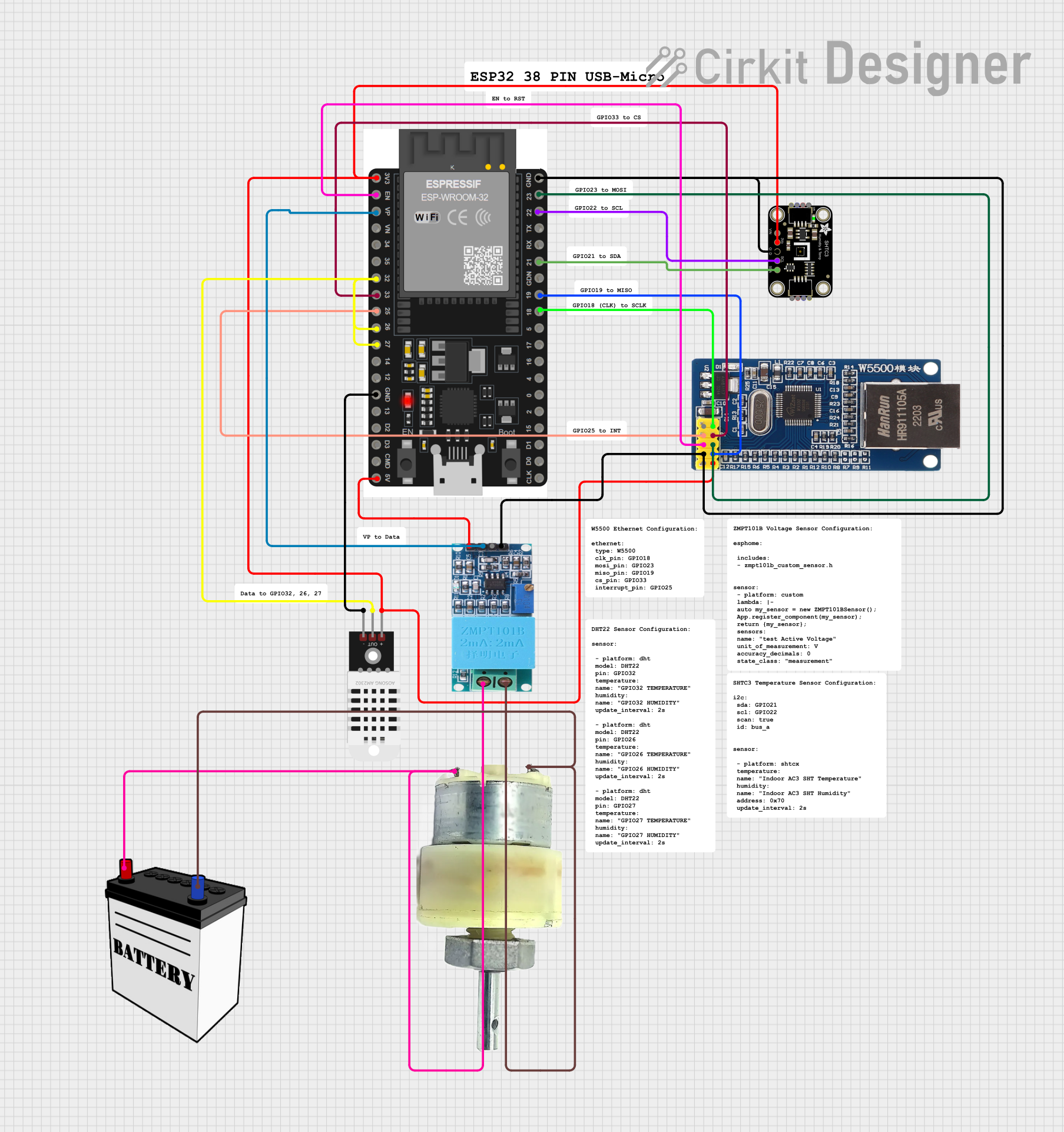
Circuit Documentation
Summary
This document provides a detailed overview of a circuit that includes an Ethernet module, temperature and humidity sensors, a voltage sensor, a geared motor, a battery, and an ESP32 microcontroller. The circuit is designed to interface various sensors and actuators with the ESP32, which processes the data and potentially communicates over Ethernet.
Component List
Module Ethernet W5500
- Description: Ethernet module for network communication.
- Pins: NC, INT, RST, GND, 5V, SCK, SS, MOSI, MISO, 3.3V
DHT22
- Description: Temperature and humidity sensor.
- Pins: +, Out, -
Adafruit SHTC3 STEMMA QT
- Description: Temperature and humidity sensor with I2C interface.
- Pins: VCC, 3.3V, GND, SCL, SDA
ZMPT101B
- Description: Voltage sensor.
- Pins: OUT, GND, VCC, NEUTRO, FASE
ESP32 38 PINS
- Description: Microcontroller with Wi-Fi and Bluetooth capabilities.
- Pins: GND, 23, 22/SCL, 1, 2, 21/SDA, 19, 18, 5, 17/TX2, 16/RX2, 4, 0, 15, D1, D0, CLK, 3V3, EN, VP, VN, 34, 35, 32, 33, 25, 26, 27, 14, 12, 13, D2, D3, 11, 5V/VIN
12V Geared Motor
- Description: Motor powered by a 12V supply.
- Pins: Terminal 1, Terminal 2
12V Battery
- Description: Power supply for the circuit.
- Pins: VCC, GND
Wiring Details
Module Ethernet W5500
- INT connected to ESP32 Pin 25
- RST connected to ESP32 Pin EN
- GND connected to GND of Adafruit SHTC3 STEMMA QT, ESP32, and ZMPT101B
- SCK connected to ESP32 Pin 18
- SS connected to ESP32 Pin 33
- MOSI connected to ESP32 Pin 23
- MISO connected to ESP32 Pin 19
- 3.3V connected to 3.3V of DHT22, Adafruit SHTC3 STEMMA QT, and ESP32
DHT22
- + connected to 3.3V of Adafruit SHTC3 STEMMA QT, Module Ethernet W5500, and ESP32
- Out connected to ESP32 Pins 32, 26, 27
- - connected to ESP32 GND
Adafruit SHTC3 STEMMA QT
- GND connected to GND of Module Ethernet W5500, ESP32, and ZMPT101B
- SCL connected to ESP32 Pin 22/SCL
- SDA connected to ESP32 Pin 21/SDA
- 3.3V connected to 3.3V of DHT22, Module Ethernet W5500, and ESP32
ZMPT101B
- OUT connected to ESP32 Pin VP
- GND connected to GND of Module Ethernet W5500, Adafruit SHTC3 STEMMA QT, and ESP32
- VCC connected to ESP32 Pin 5V/VIN
- NEUTRO connected to 12V Battery VCC and 12V Geared Motor Terminal 2
- FASE connected to 12V Battery GND and 12V Geared Motor Terminal 1
ESP32 38 PINS
- GND connected to GND of Module Ethernet W5500, Adafruit SHTC3 STEMMA QT, and ZMPT101B
- 3V3 connected to 3.3V of DHT22, Adafruit SHTC3 STEMMA QT, and Module Ethernet W5500
- 5V/VIN connected to ZMPT101B VCC
- Pin 25 connected to Module Ethernet W5500 INT
- Pin EN connected to Module Ethernet W5500 RST
- Pin 18 connected to Module Ethernet W5500 SCK
- Pin 33 connected to Module Ethernet W5500 SS
- Pin 23 connected to Module Ethernet W5500 MOSI
- Pin 19 connected to Module Ethernet W5500 MISO
- Pin VP connected to ZMPT101B OUT
- Pins 32, 26, 27 connected to DHT22 Out
- Pin 22/SCL connected to Adafruit SHTC3 STEMMA QT SCL
- Pin 21/SDA connected to Adafruit SHTC3 STEMMA QT SDA
12V Geared Motor
- Terminal 1 connected to 12V Battery GND and ZMPT101B FASE
- Terminal 2 connected to 12V Battery VCC and ZMPT101B NEUTRO
12V Battery
- VCC connected to 12V Geared Motor Terminal 2 and ZMPT101B NEUTRO
- GND connected to 12V Geared Motor Terminal 1 and ZMPT101B FASE
Documented Code
Module Ethernet W5500 Code
void setup() {
  // put your setup code here, to run once:

}

void loop() {
  // put your main code here, to run repeatedly:

}
Documentation File
- File Name: documentation.txt
- Content: (Empty)
This concludes the detailed documentation of the circuit, including the summary, component list, wiring details, and code.