
Arduino UNO RFID Access Control System with LED Indicators and Servo Motor
View and Edit Project In Cirkit Designer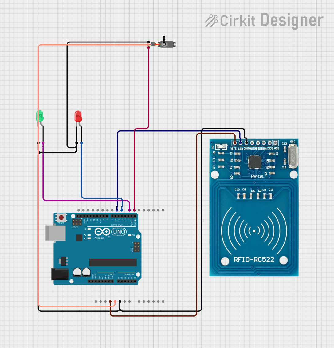
Circuit Documentation
Summary
This circuit involves an Arduino UNO microcontroller interfaced with an RFID-RC522 module, two LEDs (red and green), and a servo motor. The circuit is designed to read RFID cards. When a card is recognized, the green LED lights up, and the servo motor rotates 180 degrees. If the card reading fails, the red LED lights up.
Component List
Arduino UNO
- Description: A microcontroller board based on the ATmega328P.
- Pins: UNUSED, IOREF, Reset, 3.3V, 5V, GND, Vin, A0, A1, A2, A3, A4, A5, SCL, SDA, AREF, D13, D12, D11, D10, D9, D8, D7, D6, D5, D4, D3, D2, D1, D0
RFID-RC522
- Description: A low-cost RFID module that uses the MFRC522 IC.
- Pins: VCC (3.3V), RST, GND, IRQ, MISO, MOSI, SCK, SDA
LED: Two Pin (red)
- Description: A standard red LED.
- Pins: cathode, anode
LED: Two Pin (green)
- Description: A standard green LED.
- Pins: cathode, anode
Servo
- Description: A standard servo motor.
- Pins: GND, VCC, PWM
Wiring Details
Arduino UNO
- 3.3V: Connected to VCC (3.3V) of RFID-RC522
- 5V: Connected to VCC of Servo
- GND: Connected to GND of RFID-RC522, GND of Servo, cathode of red LED, and cathode of green LED
- D9: Connected to RST of RFID-RC522
- D8: Connected to anode of red LED
- D7: Connected to anode of green LED
- D6: Connected to PWM of Servo
RFID-RC522
- VCC (3.3V): Connected to 3.3V of Arduino UNO
- RST: Connected to D9 of Arduino UNO
- GND: Connected to GND of Arduino UNO
LED: Two Pin (red)
- cathode: Connected to GND of Arduino UNO
- anode: Connected to D8 of Arduino UNO
LED: Two Pin (green)
- cathode: Connected to GND of Arduino UNO
- anode: Connected to D7 of Arduino UNO
Servo
- GND: Connected to GND of Arduino UNO
- VCC: Connected to 5V of Arduino UNO
- PWM: Connected to D6 of Arduino UNO
Code Documentation
Arduino UNO Code
/*
 * This Arduino sketch initializes the RFID-RC522 module and turns on a green
 * LED when a card is recognized. If the card reading fails, a red LED is
 * turned on. Additionally, when the green LED is turned on, a servo motor
 * rotates 180 degrees.
 */

#include <SPI.h>
#include <MFRC522.h>
#include <Servo.h>

#define RST_PIN 9
#define SS_PIN 10
#define GREEN_LED_PIN 7
#define RED_LED_PIN 8
#define SERVO_PIN 6

MFRC522 mfrc522(SS_PIN, RST_PIN); // Create MFRC522 instance
Servo myServo; // Create Servo instance

void setup() {
  Serial.begin(9600); // Initialize serial communications
  SPI.begin(); // Init SPI bus
  mfrc522.PCD_Init(); // Init MFRC522
  pinMode(GREEN_LED_PIN, OUTPUT); // Set green LED pin as output
  pinMode(RED_LED_PIN, OUTPUT); // Set red LED pin as output
  digitalWrite(GREEN_LED_PIN, LOW); // Turn off green LED initially
  digitalWrite(RED_LED_PIN, LOW); // Turn off red LED initially
  myServo.attach(SERVO_PIN); // Attach servo to pin
  myServo.write(0); // Initialize servo position to 0 degrees
  Serial.println("Place your card to the reader...");
}

void loop() {
  // Look for new cards
  if (!mfrc522.PICC_IsNewCardPresent()) {
    return;
  }

  // Select one of the cards
  if (!mfrc522.PICC_ReadCardSerial()) {
    Serial.println("Card read failed!");
    digitalWrite(RED_LED_PIN, HIGH);
    delay(1000); // Keep red LED on for 1 second
    digitalWrite(RED_LED_PIN, LOW);
    return;
  }

  // If a card is detected, turn on the green LED and rotate servo
  Serial.println("Card detected!");
  digitalWrite(GREEN_LED_PIN, HIGH);
  myServo.write(180); // Rotate servo to 180 degrees
  delay(1000); // Keep green LED on for 1 second
  digitalWrite(GREEN_LED_PIN, LOW);
  myServo.write(0); // Reset servo to 0 degrees
}
RFID-RC522 Code
void setup() {
  // put your setup code here, to run once:

}

void loop() {
  // put your main code here, to run repeatedly:

}
This documentation provides a comprehensive overview of the circuit, including the components used, their wiring details, and the code running on the microcontroller.