ESP32-Based Cellular and GPS Tracking System with User Interface
Circuit Documentation
Summary
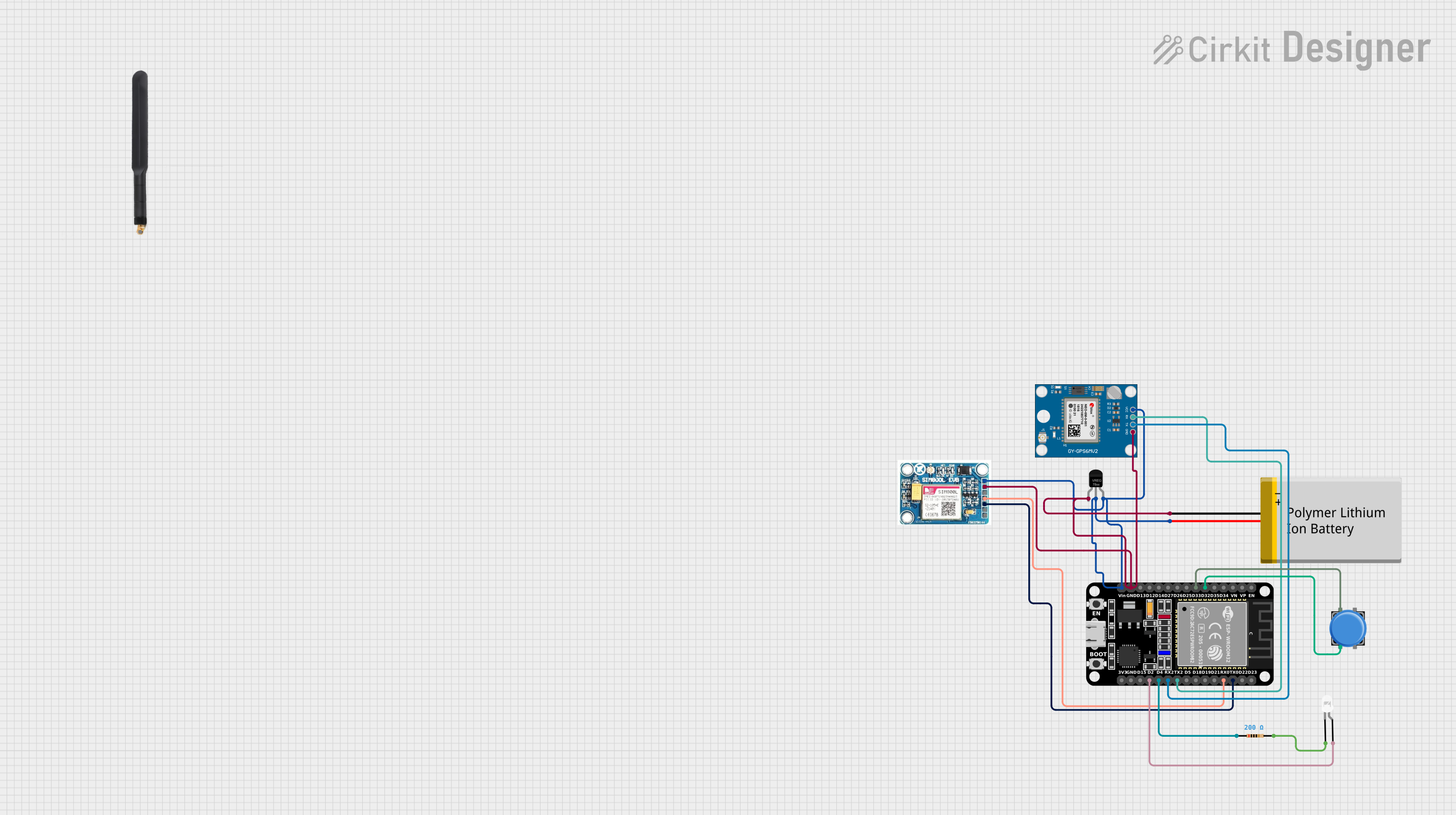
The circuit in question appears to be a communication and tracking system that utilizes a GSM module (SIM 800L V2.0) for cellular connectivity, an ESP32 microcontroller for processing and control, a GPS module (Neo 6M) for location tracking, and a Polymer Lithium Ion Battery for power supply. Additional components include a pushbutton for user input, an LED for visual output, a voltage regulator to maintain stable voltage levels, and a resistor to limit current to the LED. The circuit is designed to interface the GSM module with the ESP32 for data communication, use the GPS module for location tracking, and provide user interaction through the pushbutton and visual feedback via the LED.
Component List
SIM 800L V2.0 GSM Module
- GSM cellular communication module
- Pins: SIM_TXD, VDD, SIM.RXD, 5V/4V, GND, RST
ESP32 (30 pin) Microcontroller
- 32-bit microcontroller with Wi-Fi and Bluetooth capabilities
- Pins: EN, VP, VN, D34, D35, D32, D33, D25, D26, D27, D14, D12, D13, GND, Vin, D23, D22, TX0, RX0, D21, D19, D18, D5, TX2, RX2, D4, D2, D15, 3V3
Polymer Lithium Ion Battery - Generic
- Rechargeable battery for power supply
- Pins: GND, VCC
Neo 6M GPS Module
- GPS receiver module for location tracking
- Pins: GND, TX, RX, VCC
Pushbutton
- Standard pushbutton for user input
- Pins: Pin 2, Pin 1, Pin 3, Pin 4
LED: Two Pin (white)
- White LED for visual indication
- Pins: cathode, anode
Voltage Regulator
- Component to regulate input voltage to a stable output voltage
- Pins: GND, IN, OUT
Resistor
- Passive component to limit current
- Resistance: 200 Ohms
- Pins: pin1, pin2
4G Antenna
- Antenna for enhancing GSM module signal reception
- Pins: Connection
Wiring Details
SIM 800L V2.0 GSM Module
- SIM_TXD connected to ESP32 RX0
- SIM.RXD connected to ESP32 TX0
- 5V/4V connected to the power supply net (Battery VCC, ESP32 Vin, Voltage Regulator IN/OUT)
- GND connected to the common ground net
ESP32 (30 pin) Microcontroller
- RX0 connected to SIM 800L V2.0 GSM SIM_TXD
- TX0 connected to SIM 800L V2.0 GSM SIM.RXD
- Vin connected to the power supply net
- GND connected to the common ground net
- D32 connected to Pushbutton Pin 2
- D33 connected to Pushbutton Pin 1
- TX2 connected to Neo 6M GPS Module RX
- RX2 connected to Neo 6M GPS Module TX
- D4 connected to Resistor pin1
- D2 connected to LED anode
Polymer Lithium Ion Battery - Generic
- VCC connected to the power supply net
- GND connected to the common ground net
Neo 6M GPS Module
- VCC connected to the power supply net
- GND connected to the common ground net
- TX connected to ESP32 RX2
- RX connected to ESP32 TX2
Pushbutton
- Pin 2 connected to ESP32 D32
- Pin 1 connected to ESP32 D33
LED: Two Pin (white)
- Anode connected to ESP32 D2
- Cathode connected to Resistor pin2
Voltage Regulator
- IN connected to the power supply net
- OUT connected to the power supply net
- GND connected to the common ground net
Resistor
- Pin1 connected to ESP32 D4
- Pin2 connected to LED cathode
Documented Code
No code has been provided for the microcontroller(s) in the circuit. The documentation of the code would typically include a description of the functionality, setup, and main loop, along with any functions or libraries used. Since there is no code to document, this section remains empty.