ESP8266 Wi-Fi Controlled Smart Light System with IR Sensors and LDR
Circuit Documentation
Summary
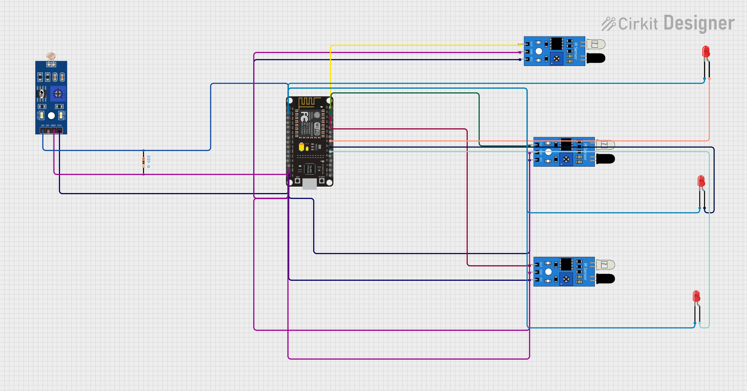
This circuit is designed to interface an ESP8266 NodeMCU microcontroller with multiple IR sensors, an LDR (Light Dependent Resistor), and several LEDs. The ESP8266 NodeMCU reads inputs from the IR sensors and the LDR, processes the data, and controls the LEDs accordingly. Additionally, the microcontroller communicates with ThingSpeak to log data and receive commands.
Component List
LDR (Light Dependent Resistor)
- Pins: A0, D0, GND, VCC
- Description: A sensor that changes its resistance based on the light intensity.
- Purpose: To measure ambient light levels.
ESP8266 NodeMCU
- Pins: D0, D1, D2, D3, D4, 3V3, GND, D5, D6, D7, D8, RX, TX, A0, RSV, SD3, SD2, SD1, CMD, SD0, CLK, EN, RST, VIN
- Description: A microcontroller with built-in WiFi capabilities.
- Purpose: To read sensor data, control LEDs, and communicate with ThingSpeak.
IR Sensor
- Pins: out, gnd, vcc
- Description: An infrared sensor used to detect objects.
- Purpose: To detect the presence of objects.
Resistor
- Pins: pin1, pin2
- Description: A 220 Ohm resistor.
- Purpose: To limit current to the LEDs.
LED: Two Pin (red)
- Pins: cathode, anode
- Description: A red LED.
- Purpose: To provide visual feedback based on sensor inputs.
Wiring Details
LDR (Light Dependent Resistor)
- A0: Connected to A0 of ESP8266 NodeMCU
- GND: Connected to GND of ESP8266 NodeMCU
- VCC: Connected to VIN of ESP8266 NodeMCU
ESP8266 NodeMCU
- D0: Connected to out of IR Sensor 1
- D1: Connected to out of IR Sensor 2
- D2: Connected to out of IR Sensor 3
- D5: Connected to anode of LED 1 and LED 2
- D6: Connected to anode of LED 3
- D7: Connected to anode of LED 4
- A0: Connected to A0 of LDR
- GND: Connected to gnd of IR Sensor 1, IR Sensor 2, IR Sensor 3, and LDR
- VIN: Connected to vcc of IR Sensor 1, IR Sensor 2, IR Sensor 3, and LDR
IR Sensor 1
- out: Connected to D0 of ESP8266 NodeMCU
- gnd: Connected to GND of ESP8266 NodeMCU
- vcc: Connected to VIN of ESP8266 NodeMCU
IR Sensor 2
- out: Connected to D1 of ESP8266 NodeMCU
- gnd: Connected to GND of ESP8266 NodeMCU
- vcc: Connected to VIN of ESP8266 NodeMCU
IR Sensor 3
- out: Connected to D2 of ESP8266 NodeMCU
- gnd: Connected to GND of ESP8266 NodeMCU
- vcc: Connected to VIN of ESP8266 NodeMCU
LED 1
- anode: Connected to D5 of ESP8266 NodeMCU
- cathode: Connected to RSV of ESP8266 NodeMCU
LED 2
- anode: Connected to D5 of ESP8266 NodeMCU
- cathode: Connected to RSV of ESP8266 NodeMCU
LED 3
- anode: Connected to D6 of ESP8266 NodeMCU
- cathode: Connected to RSV of ESP8266 NodeMCU
LED 4
- anode: Connected to D7 of ESP8266 NodeMCU
- cathode: Connected to RSV of ESP8266 NodeMCU
Code Documentation
#include <ESP8266WiFi.h>;
#include <WiFiClient.h>;
#include <ThingSpeak.h>;

const char* ssid = "CircuitLoop";
const char* password = "circuitdigest101";

WiFiClient client;

unsigned long myChannelNumber = 795820;
const char * myWriteAPIKey = "FZTOUARV558GRZ8J";
const char * myReadAPIKey = "T52GT3QQOQBVPG4V";
int D0;
int D1;
int D2;
int D3;
int D4;
int D5;
int D6;
int D7;

int led_1;
int led_2;
int led_3;

int ir1 = D0;
int led1 = D5;

int ir2 = D1;
int led2 = D6;

int ir3 = D2;
int led3 = D7;

int ldr = A0;
int val =0;

void setup() {
  Serial.begin(9600);
  delay(10);
  pinMode(ir1,INPUT);
  pinMode(led1,OUTPUT);

  pinMode(ir2,INPUT);
  pinMode(led2,OUTPUT);

  pinMode(ir3,INPUT);
  pinMode(led3,OUTPUT);

  WiFi.begin(ssid, password);
  ThingSpeak.begin(client);
}

void loop() {
  int s1 = digitalRead(ir1);
  int s2 = digitalRead(ir2);
  int s3 = digitalRead(ir3);
  s3 = not(s3);

  val = analogRead(ldr);

  Serial.print(s1);
  Serial.print(":");
  Serial.print(s2);
  Serial.print(":");
  Serial.print(s3);
  Serial.print("  ");
  Serial.println(val);
  if(val<800)
  {
    if(s1==0)
    {
      digitalWrite(led1,LOW);
    }
    else
    {
      digitalWrite(led1,HIGH);
    }
    if(s2==0)
    {
      digitalWrite(led2,LOW);
    }
    else
    {
      digitalWrite(led2,HIGH);
    }

    if(s3==0)
    {
      digitalWrite(led3,LOW);
    }
    else
    {
      digitalWrite(led3,HIGH);
    }
  }
  else
  {
    digitalWrite(led1,LOW);
    digitalWrite(led2,LOW);
    digitalWrite(led3,LOW);
  }

  ThingSpeak.writeField(myChannelNumber, 1,val, myWriteAPIKey);
  ThingSpeak.writeField(myChannelNumber, 2,s1, myWriteAPIKey);
  ThingSpeak.writeField(myChannelNumber, 3,s2, myWriteAPIKey);
  ThingSpeak.writeField(myChannelNumber, 4,s3, myWriteAPIKey);
  ThingSpeak.writeField(myChannelNumber, 5,led1, myWriteAPIKey);
  ThingSpeak.writeField(myChannelNumber, 6,led2, myWriteAPIKey);
  ThingSpeak.writeField(myChannelNumber, 7,led3, myWriteAPIKey);

  led_1 = ThingSpeak.readIntField(myChannelNumber, 5, myReadAPIKey);
  led_2 = ThingSpeak.readIntField(myChannelNumber, 6, myReadAPIKey);
  led_3 = ThingSpeak.readIntField(myChannelNumber, 7, myReadAPIKey);

  if(led_1==1)
  {
    digitalWrite(led1,HIGH);
  }
  else
  {
    digitalWrite(led1,LOW);
  }

  if(led_2==1)
  {
    digitalWrite(led2,HIGH);
  }
  else
  {
    digitalWrite(led2,LOW);
  }

  if(led_3==1)
  {
    digitalWrite(led3,HIGH);
  }
  else
  {
    digitalWrite(led3,LOW);
  }
}
This code initializes the ESP8266 NodeMCU, connects it to a WiFi network, and sets up the ThingSpeak client. It reads the states of the IR sensors and the LDR, controls the LEDs based on the sensor inputs, and logs the data to ThingSpeak. The code also reads commands from ThingSpeak to control the LEDs remotely.