Cirkit Designer
Your all-in-one circuit design IDE
Home /
Project Documentation
ESP32 Nano and APC220-Based Wireless Home Security System with RGB LED and Buzzer Alerts
Circuit Documentation
Summary
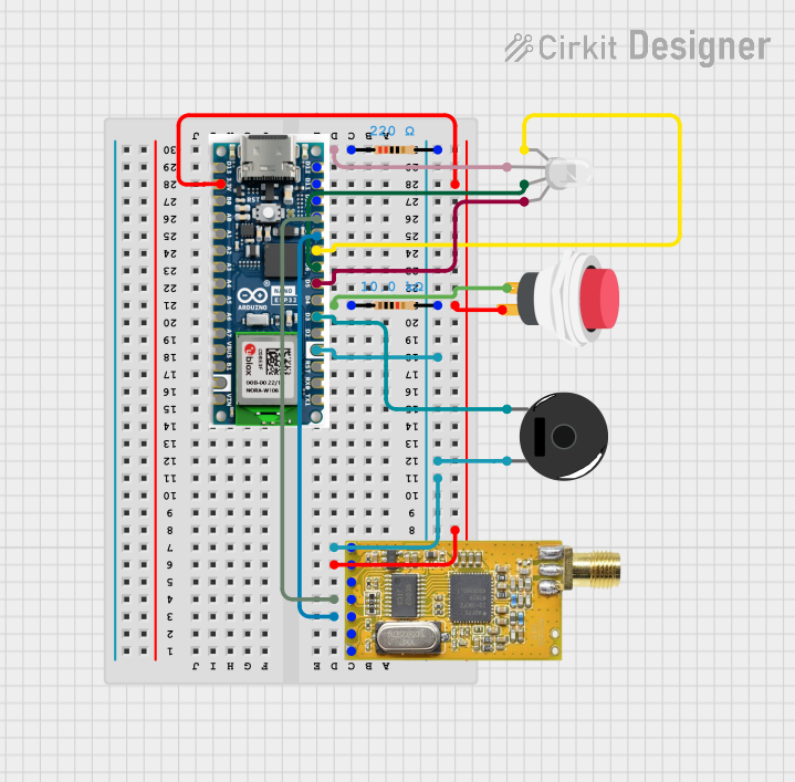
This document provides a detailed overview of a security system circuit designed using an Arduino Nano ESP32 microcontroller. The system includes an APC220 wireless communication module, an RGB LED, a push switch, a piezo buzzer, and resistors. The circuit is programmed to handle various security functions such as arming/disarming the system, alerting intrusions, and sending email notifications.
Component List
APC220
- Description: Wireless communication module
- Pins: GND, VCC, EN, RXD, TXD, AUX, SET
Arduino Nano ESP32
- Description: Microcontroller
- Pins: D12, D11, D10, D9, D8, D7, D6, D5, D4, D3, D2, GND, RST, RX0, TX1, D13, 3.3V, B0, A0, A1, A2, A3, A4, A5, A6, A7, VBUS, B1, VIN
RGB LED (Wokwi compatible)
- Description: RGB LED
- Pins: R, COM, G, B
2Pin Push Switch
- Description: Push button switch
- Pins: Input +, Output +
Piezo Buzzer
- Description: Buzzer for sound alerts
- Pins: pin 1, pin 2
Resistor (220 Ohms)
- Description: Resistor
- Pins: pin1, pin2
- Properties: Resistance: 220 Ohms
Resistor (10k Ohms)
- Description: Resistor
- Pins: pin1, pin2
- Properties: Resistance: 10k Ohms
Wiring Details
APC220
- TXD: Not connected
- RXD: Connected to D9 of Arduino Nano ESP32
- VCC: Connected to Output + of 2Pin Push Switch and 3.3V of Arduino Nano ESP32
- GND: Connected to pin2 of 220 Ohms Resistor, pin2 of 10k Ohms Resistor, pin 2 of Piezo Buzzer, and GND of Arduino Nano ESP32
Arduino Nano ESP32
- D9: Connected to RXD of APC220
- 3.3V: Connected to Output + of 2Pin Push Switch and VCC of APC220
- GND: Connected to pin2 of 220 Ohms Resistor, pin2 of 10k Ohms Resistor, pin 2 of Piezo Buzzer, and GND of APC220
- D7: Connected to R of RGB LED
- D6: Connected to G of RGB LED
- D5: Connected to B of RGB LED
- D3: Connected to pin 1 of Piezo Buzzer
RGB LED (Wokwi compatible)
- R: Connected to D7 of Arduino Nano ESP32
- COM: Connected to pin1 of 220 Ohms Resistor
- G: Connected to D6 of Arduino Nano ESP32
- B: Connected to D5 of Arduino Nano ESP32
2Pin Push Switch
- Input +: Connected to pin1 of 10k Ohms Resistor
- Output +: Connected to VCC of APC220 and 3.3V of Arduino Nano ESP32
Piezo Buzzer
- pin 1: Connected to D3 of Arduino Nano ESP32
- pin 2: Connected to GND of Arduino Nano ESP32 and GND of APC220
Resistor (220 Ohms)
- pin1: Connected to COM of RGB LED
- pin2: Connected to GND of Arduino Nano ESP32 and GND of APC220
Resistor (10k Ohms)
- pin1: Connected to Input + of 2Pin Push Switch
- pin2: Connected to GND of Arduino Nano ESP32 and GND of APC220
Code Documentation
Project: Fleapit Security System - Homebase (ESP32 Nano)
- Date: 26-10-2024
- Version:
- 0.1 (26-10-2024) work in progress
- 1.0 (22-12-2024) working version
- 1.1 (23-12-2024) minor improvements, added ALIVE checking, added beep on mode change
- 1.4 (26-12-2024) created one function for (dis)arming system, minor adjustments to function parameters
- Description: This is the home base ESP32 Arduino Nano code for the security of the fleapit with the aid of the APC220 wireless communication module.
Code
// LIBRARYS
#include <Arduino.h>
#include <SoftwareSerial.h>
#include <WiFi.h>
#include <ESP_Mail_Client.h>

// DEFINITIONS
#define MAX_NUMBER_OF_MESSAGES    4
#define TIME_BETWEEN_ALIVE_CHECK  3000 // milliseconds
#define ON                        1
#define OFF                       0
#define APC220_SPEED              9600 // baud
#define APC220_RX_PIN             9
#define APC220_TX_PIN             8
#define ARMED_LED_PIN             7 // Rgb led (blinking)
#define DISARMED_LED_PIN          6 // rGb led (blinking)
#define ALERT_LED_PIN             5 // rgB led (blinking)
#define MODE_BUTTON_PIN           4
#define ALERT_BUZZER_PIN          3

// Some tones
#define TONE_B4                   494 // Hz
#define TONE_D4                   294 // Hz

// WIFI settings
#define WIFI_SSID "TP-Link_Guest_D400"
#define WIFI_PASSWORD "CrazyFamily"

// EMAIL settings
// The smtp host name e.g. smtp.gmail.com for GMail or smtp.office365.com for Outlook or smtp.mail.yahoo.com
#define SMTP_HOST "smtp.gmail.com"
#define SMTP_PORT 465

// The sign in credentials
#define AUTHOR_EMAIL "esp32.intruderalert@gmail.com"
#define AUTHOR_PASSWORD "pcbq mqbo wzsx jftk"

// Recipient's email
#define RECIPIENT_EMAIL "rpaverheijen@hotmail.com"

// FUNCTIONS
void BlinkLed(const byte, const int, const int);
void ArmSystem(const bool);
void AlertOn(const byte, const byte, const int);
void sendEmail(void);
void ShortBeep(void);

// VARIABLES
SoftwareSerial homebase(APC220_TX_PIN, APC220_RX_PIN);
String sendMessage, receivedMessage;
bool systemArmed = OFF;
unsigned long fleapitLastTimeAlive = 0; // Used for checking if the communication is still active
String messages[MAX_NUMBER_OF_MESSAGES] = { "INTRUDER ALERT", "STILL ALIVE!", "SYSTEM ARMED", "SYSTEM DISARMED" }; // All the messages that can be received from the fleapit
byte messageNumber = -1;

void loop(void) {
  // Check for button press
  if (digitalRead(MODE_BUTTON_PIN)) {
    while (digitalRead(MODE_BUTTON_PIN)) { ; }
    systemArmed ? ArmSystem(OFF) : ArmSystem(ON);
  }

  // Checking for messages
  if (homebase.available()) {
    receivedMessage = homebase.readStringUntil('\n');
    for (byte i = 0; i < MAX_NUMBER_OF_MESSAGES; i++) {
      if ( receivedMessage == messages[i] ) {
        messageNumber = i;
        break;
      }
    }
    switch (messageNumber) {
      case 0: // "INTRUDER ALERT"
        AlertOn(ALERT_LED_PIN, ALERT_BUZZER_PIN, 10);
        sendEmail();
        AlertOn(ALERT_LED_PIN, ALERT_BUZZER_PIN, 500);
        break;
      case 1: // "STILL ALIVE!"
        systemArmed ? BlinkLed(ARMED_LED_PIN, 1, 200) : BlinkLed(DISARMED_LED_PIN, 1, 200);
        break;
      case 2: // "SYSTEM ARMED"
        ShortBeep();
        BlinkLed(ARMED_LED_PIN, 5, 200);
        systemArmed = ON;
        break;
      case 3: // "SYSTEM DISARMED"
        ShortBeep();
        BlinkLed(DISARMED_LED_PIN, 5, 200);
        systemArmed = OFF;
        break;
    }
  }

  // Checking if it is time to ask life status
  if ( millis() > (fleapitLastTimeAlive + TIME_BETWEEN_ALIVE_CHECK) ) {
    sendMessage = "STILL ALIVE?";
    homebase.print(sendMessage + "\n");
    fleapitLastTimeAlive = millis();
  }
}

void setup(void) {
  homebase.begin(APC220_SPEED);
  pinMode(ARMED_LED_PIN, OUTPUT);
  pinMode(DISARMED_LED_PIN, OUTPUT);
  pinMode(ALERT_LED_PIN, OUTPUT);
  pinMode(MODE_BUTTON_PIN, INPUT);
  // On (re)boot the system is set to ARMED !!!
  ArmSystem(ON);
}

void BlinkLed(const byte ledPin, const int blinks, const int delayTime) {
  // This function will blink the led connected to ledPin a blink times with a delay time of