
Arduino Nano and ESP8266 Wi-Fi Controlled Weather Station with LCD Display
View and Edit Project In Cirkit Designer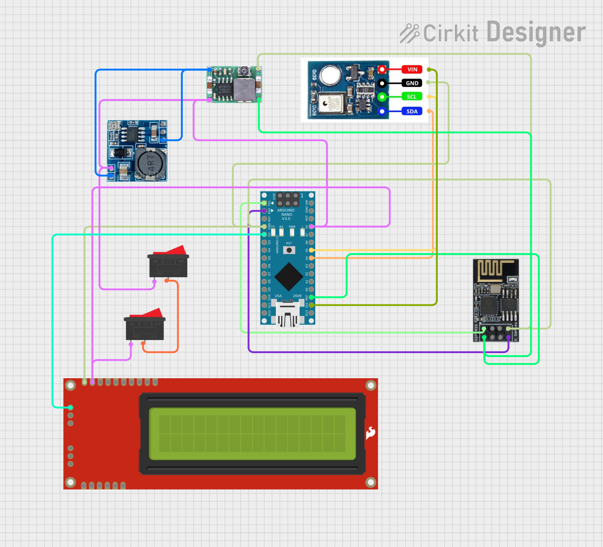
Circuit Documentation
Summary
This circuit involves a power management system using step-down modules, an Arduino Nano microcontroller, a WiFi module, an LCD display, and a temperature and humidity sensor. The circuit is designed to manage power distribution, control, and data display.
Component List
Step down Module
- Description: Converts higher voltage to a lower voltage.
- Pins: 24v IN+, GND, 12v IN+, 5v OUT+, 5v OUT-
Mini-360 DC-DC Step Down Buck Converter
- Description: A compact DC-DC step-down converter.
- Pins: Input -, Input +, Output +, Output -
AHT10
- Description: Temperature and humidity sensor.
- Pins: Vcc, Gnd, SCL, SDA
Arduino Nano
- Description: A small, complete, and breadboard-friendly board based on the ATmega328.
- Pins: D1/TX, D0/RX, RESET, GND, D2, D3, D4, D5, D6, D7, D8, D9, D10, D11/MOSI, D12/MISO, VIN, 5V, A7, A6, A5, A4, A3, A2, A1, A0, AREF, 3V3, D13/SCK
Rocker Switch
- Description: A simple on/off switch.
- Pins: 1, 2
Wifi module ESP8266-01
- Description: A self-contained WiFi networking solution.
- Pins: RX, GPIO0, GPIO2, GND, +3V3, Reset, CH-PD Chip power down, TX
Serial Enabled 16x2 LCD - Black on Green 5V
- Description: A 16x2 character LCD with serial interface.
- Pins: GND, RX, VDD, RS, R/W, E, DB4, DB5, DB6, DB7, BL+, PGM, PGC, PGD, VPP
Wiring Details
Step down Module
- GND: Connected to Mini-360 DC-DC Step Down Buck Converter (Input -) and Step down Module (5v OUT-)
- 5v OUT+: Connected to Mini-360 DC-DC Step Down Buck Converter (Input +), Rocker Switch (1), Arduino Nano (5V), Serial Enabled 16x2 LCD (VDD), and Rocker Switch (1)
- 5v OUT-: Connected to Mini-360 DC-DC Step Down Buck Converter (Input -) and Step down Module (GND)
Mini-360 DC-DC Step Down Buck Converter
- Input -: Connected to Step down Module (GND) and Step down Module (5v OUT-)
- Input +: Connected to Step down Module (5v OUT+), Rocker Switch (1), Arduino Nano (5V), Serial Enabled 16x2 LCD (VDD), and Rocker Switch (1)
- Output +: Connected to Arduino Nano (AREF) and Wifi module ESP8266-01 (+3V3)
- Output -: Connected to Arduino Nano (GND), Serial Enabled 16x2 LCD (GND), Wifi module ESP8266-01 (GND), and AHT10 (Gnd)
AHT10
- Vcc: Connected to Arduino Nano (3V3)
- Gnd: Connected to Mini-360 DC-DC Step Down Buck Converter (Output -)
- SCL: Connected to Arduino Nano (A5)
- SDA: Connected to Arduino Nano (A4)
Arduino Nano
- 5V: Connected to Mini-360 DC-DC Step Down Buck Converter (Input +), Rocker Switch (1), Step down Module (5v OUT+), and Serial Enabled 16x2 LCD (VDD)
- GND: Connected to Mini-360 DC-DC Step Down Buck Converter (Output -), Serial Enabled 16x2 LCD (GND), Wifi module ESP8266-01 (GND), and AHT10 (Gnd)
- AREF: Connected to Mini-360 DC-DC Step Down Buck Converter (Output +)
- 3V3: Connected to AHT10 (Vcc)
- D2: Connected to Serial Enabled 16x2 LCD (RX)
- A5: Connected to AHT10 (SCL)
- A4: Connected to AHT10 (SDA)
- D1/TX: Connected to Wifi module ESP8266-01 (RX)
- D0/RX: Connected to Wifi module ESP8266-01 (TX)
Rocker Switch
- 1: Connected to Mini-360 DC-DC Step Down Buck Converter (Input +), Step down Module (5v OUT+), Arduino Nano (5V), Serial Enabled 16x2 LCD (VDD), and Rocker Switch (1)
- 2: Connected to Rocker Switch (2)
Wifi module ESP8266-01
- +3V3: Connected to Mini-360 DC-DC Step Down Buck Converter (Output +)
- GND: Connected to Mini-360 DC-DC Step Down Buck Converter (Output -)
- RX: Connected to Arduino Nano (D1/TX)
- TX: Connected to Arduino Nano (D0/RX)
Serial Enabled 16x2 LCD - Black on Green 5V
- VDD: Connected to Mini-360 DC-DC Step Down Buck Converter (Input +), Rocker Switch (1), Step down Module (5v OUT+), and Arduino Nano (5V)
- GND: Connected to Mini-360 DC-DC Step Down Buck Converter (Output -)
- RX: Connected to Arduino Nano (D2)
Documented Code
Arduino Nano Code
void setup() {
  // put your setup code here, to run once:

}

void loop() {
  // put your main code here, to run repeatedly:

}
This code is a basic template for the Arduino Nano. The setup() function runs once when the microcontroller is powered on or reset, and the loop() function runs continuously. You can add your specific functionality within these functions.