
Circuit Documentation
Summary of the Circuit
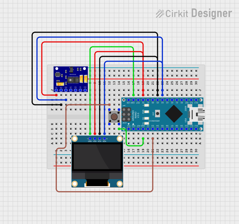
This circuit is designed to measure heart rate and blood oxygen saturation (SpO2) using a MAX30102 sensor, display the data on a 0.96" OLED screen, and allow user interaction through a pushbutton. The Arduino Nano serves as the central microcontroller to process the sensor data, control the OLED display, and manage user input.
Component List
Arduino Nano
- Description: A compact microcontroller board based on the ATmega328P.
- Pins: D1/TX, D0/RX, RESET, GND, D2, D3, D4, D5, D6, D7, D8, D9, D10, D11/MOSI, D12/MISO, VIN, 5V, A7, A6, A5, A4, A3, A2, A1, A0, AREF, 3V3, D13/SCK.
0.96" OLED
- Description: A small display for visual output.
- Pins: GND, VDD, SCK, SDA.
Pushbutton
- Description: A simple pushbutton for user input.
- Pins: Pin 3 (out), Pin 4 (out), Pin 1 (in), Pin 2 (in).
MAX30102 Heart Rate and Oxygen Sensor
- Description: A sensor for measuring heart rate and blood oxygen levels.
- Pins: VIN, SCL, SDA, INT, IRQ, RD, GND.
Wiring Details
Arduino Nano
- 5V: Supplies power to the OLED and MAX30102 sensor.
- A5: Connected to the SCK of the OLED and SCL of the MAX30102 sensor for I2C communication.
- A4: Connected to the SDA of the OLED and SDA of the MAX30102 sensor for I2C communication.
- GND: Common ground for the OLED, Pushbutton, and MAX30102 sensor.
- D3: Connected to the input pin of the Pushbutton.
0.96" OLED
- VDD: Connected to the 5V output from the Arduino Nano.
- SCK: Connected to A5 on the Arduino Nano for I2C communication.
- SDA: Connected to A4 on the Arduino Nano for I2C communication.
- GND: Connected to the GND on the Arduino Nano.
Pushbutton
- Pin 1 (in): Connected to D3 on the Arduino Nano.
- Pin 4 (out): Connected to GND on the Arduino Nano.
MAX30102 Heart Rate and Oxygen Sensor
- VIN: Connected to the 5V output from the Arduino Nano.
- SCL: Connected to A5 on the Arduino Nano for I2C communication.
- SDA: Connected to A4 on the Arduino Nano for I2C communication.
- GND: Connected to the GND on the Arduino Nano.
Documented Code
The code for the Arduino Nano is written in C++ and is designed to work with the connected components to measure heart rate and blood oxygen saturation, display the data on the OLED, and respond to button presses.
#include "ssd1306h.h"
#include "MAX30102.h"
#include "Pulse.h"
#include <avr/pgmspace.h>
#include <EEPROM.h>
#include <avr/sleep.h>

// Definitions for bit manipulation
#ifndef cbi
#define cbi(sfr, bit) (_SFR_BYTE(sfr) &= ~_BV(bit))
#endif
#ifndef sbi
#define sbi(sfr, bit) (_SFR_BYTE(sfr) |= _BV(bit))
#endif

// Object instantiation for the OLED, sensor, and pulse processing
SSD1306 oled;
MAX30102 sensor;
Pulse pulseIR;
Pulse pulseRed;
MAFilter bpm;

// Pin definitions
#define LED LED_BUILTIN
#define BUTTON 3
#define OPTIONS 7

// Heart bitmap for display
static const uint8_t heart_bits[] PROGMEM = { /* ... */ };

// SpO2 lookup table
const uint8_t spo2_table[184] PROGMEM = { /* ... */ };

// Function to read the supply voltage
int getVCC() {
  // Implementation details...
}

// Function to print a digit on the OLED
void print_digit(int x, int y, long val, char c=' ', uint8_t field = 3,const int BIG = 2) {
  // Implementation details...
}

// Waveform class to record and display PPG waveform
class Waveform {
  // Class members and methods...
} wave;

// Global variables and function declarations
int  beatAvg;
int  SPO2, SPO2f;
int  voltage;
bool filter_for_graph = false;
bool draw_Red = false;
uint8_t pcflag =0;
uint8_t istate = 0;
uint8_t sleep_counter = 0;

void button(void) {
  // Implementation details...
}

void checkbutton() {
  // Implementation details...
}

void Display_5() {
  // Implementation details...
}

void go_sleep() {
  // Implementation details...
}

void draw_oled(int msg) {
  // Implementation details...
}

void setup(void) {
  // Setup code for the OLED, sensor, and button interrupt
}

void loop()  {
  // Main loop for processing sensor data and updating the display
}
The code includes setup and loop functions, which are standard in Arduino sketches. The setup function initializes the OLED display, the MAX30102 sensor, and sets up an interrupt for the pushbutton. The loop function continuously checks the sensor data, updates the display, and handles button presses to change display modes or enter a low-power sleep state.