
ESP32C3 Smart Home Energy Monitor with Wi-Fi Control and LED Indicators
View and Edit Project In Cirkit Designer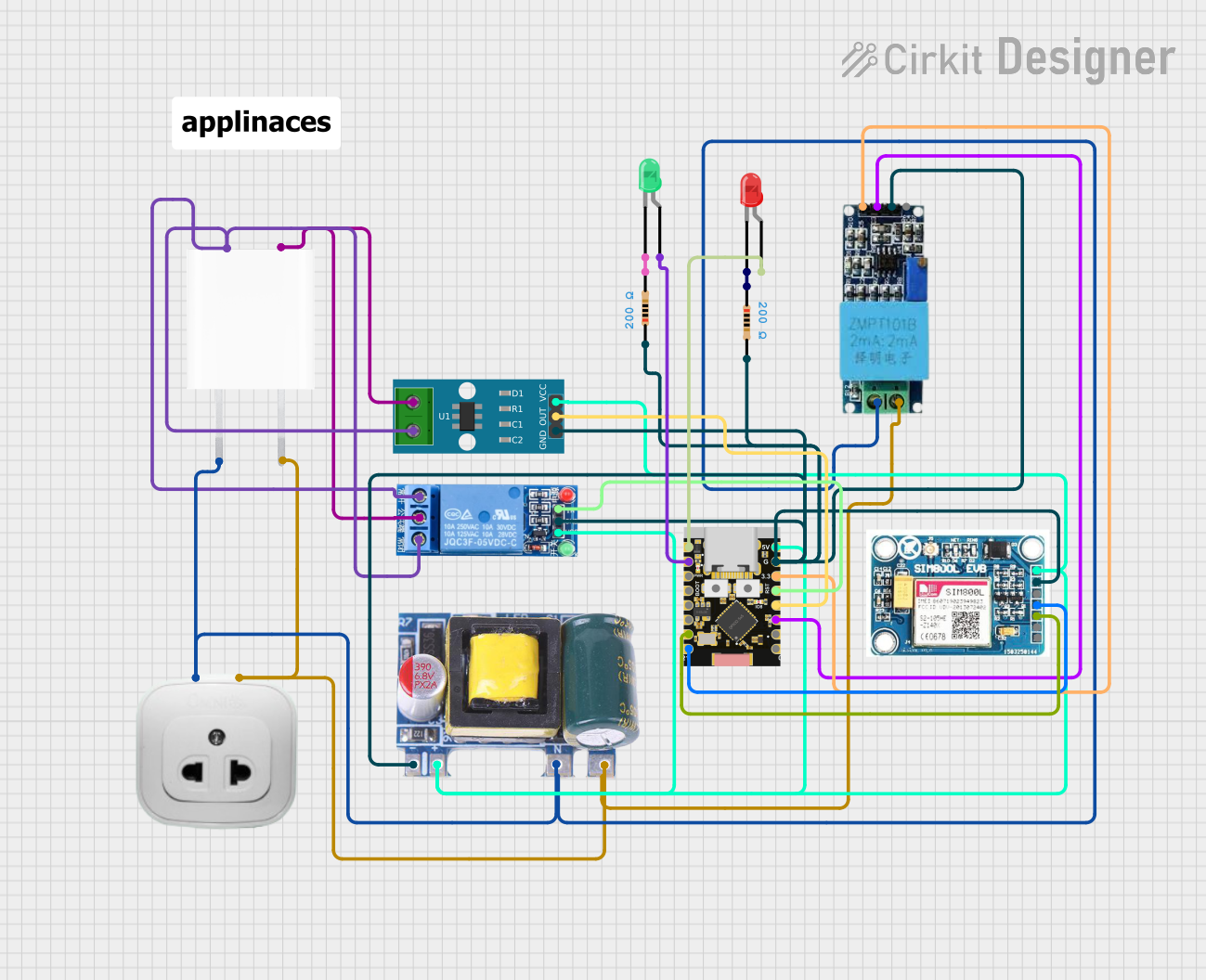
Circuit Documentation
Summary
This circuit is designed to monitor and control electrical appliances using an ESP32C3 microcontroller. It reads wattages using an ACS712 current sensor and a voltage sensor, controls appliances using a relay, and indicates WiFi connection status using LEDs. The relay is controlled via a web interface, and the red LED indicates WiFi disconnection status.
Component List
LED: Two Pin (green)
- Pins: cathode, anode
- Description: Green LED used to indicate WiFi connection status.
LED: Two Pin (red)
- Pins: cathode, anode
- Description: Red LED used to indicate WiFi disconnection status.
Resistor
- Pins: pin1, pin2
- Description: 200 Ohms resistor used in series with the green LED.
- Properties:
- Resistance: 200 Ohms
Resistor
- Pins: pin1, pin2
- Description: 200 Ohms resistor used in series with the red LED.
- Properties:
- Resistance: 200 Ohms
Voltage Sensor
- Pins: Ground, Phase, Vcc, Out, Gnd
- Description: Sensor used to measure voltage.
1 Channel Relay 5V
- Pins: VCC, GND, IN, NC, COM, NO
- Description: Relay used to control appliances.
Mini AC-DC 110V-230V to 5V 700mA Module
- Pins: GND, 5v, Neutral, Life
- Description: Power supply module to convert AC to 5V DC.
SIM 800L V2.0 GSM
- Pins: SIM_TXD, VDD, SIM.RXD, 5V/4V, GND, RST
- Description: GSM module for communication.
ACS712 Current Sensor 5A 20A 30A
- Pins: 1, 2, GND, OUT, VCC
- Description: Current sensor used to measure current.
OUTLET
- Pins: AC
- Description: AC outlet.
5V Adapter
- Pins: AC In 1, AC In 2, 5V, GND
- Description: Adapter to provide 5V power.
ESP32C3 Supermini
- Pins: GPIO05, GPIO06, GPIO07, GPIO08, GPIO09, GPIO10, GPIO20, GPIO21, GPIO00, GPIO01, GPIO02, GPIO03, GPIO04, 3.3V, GND, +5V
- Description: Microcontroller used to control the circuit.
Wiring Details
LED: Two Pin (green)
- cathode connected to Resistor pin2
- anode connected to ESP32C3 Supermini GPIO06
LED: Two Pin (red)
- cathode connected to Resistor pin1
- anode connected to ESP32C3 Supermini GPIO05
Resistor (200 Ohms)
- pin1 connected to LED: Two Pin (red) cathode
- pin2 connected to ESP32C3 Supermini GND
Resistor (200 Ohms)
- pin1 connected to ESP32C3 Supermini GND
- pin2 connected to LED: Two Pin (green) cathode
Voltage Sensor
- Ground connected to 5V Adapter AC In 2
- Phase connected to 5V Adapter AC In 1
- Vcc connected to ESP32C3 Supermini 3.3V
- Out connected to ESP32C3 Supermini GPIO02
- Gnd connected to ESP32C3 Supermini GND
1 Channel Relay 5V
- VCC connected to ESP32C3 Supermini +5V
- GND connected to ESP32C3 Supermini GND
- IN connected to ESP32C3 Supermini GPIO04
- NC connected to 5V Adapter GND
- COM connected to 5V Adapter 5V
- NO connected to 5V Adapter GND
Mini AC-DC 110V-230V to 5V 700mA Module
- GND connected to ESP32C3 Supermini GND
- 5v connected to ESP32C3 Supermini +5V
- Neutral connected to 5V Adapter AC In 2
- Life connected to 5V Adapter AC In 1
SIM 800L V2.0 GSM
- SIM_TXD connected to ESP32C3 Supermini GPIO21
- VDD not connected
- SIM.RXD connected to ESP32C3 Supermini GPIO20
- 5V/4V connected to ESP32C3 Supermini +5V
- GND connected to ESP32C3 Supermini GND
- RST not connected
ACS712 Current Sensor 5A 20A 30A
- 1 connected to 5V Adapter 5V
- 2 connected to 5V Adapter GND
- GND connected to ESP32C3 Supermini GND
- OUT connected to ESP32C3 Supermini GPIO03
- VCC connected to ESP32C3 Supermini +5V
OUTLET
- AC connected to 5V Adapter AC In 1
- AC connected to 5V Adapter AC In 2
5V Adapter
- AC In 1 connected to OUTLET AC
- AC In 2 connected to OUTLET AC
- 5V connected to ACS712 Current Sensor 5A 20A 30A 1
- GND connected to ACS712 Current Sensor 5A 20A 30A 2
ESP32C3 Supermini
- GPIO05 connected to LED: Two Pin (red) anode
- GPIO06 connected to LED: Two Pin (green) anode
- GPIO02 connected to Voltage Sensor Out
- GPIO03 connected to ACS712 Current Sensor 5A 20A 30A OUT
- GPIO04 connected to 1 Channel Relay 5V IN
- GPIO21 connected to SIM 800L V2.0 GSM SIM_TXD
- GPIO20 connected to SIM 800L V2.0 GSM SIM.RXD
- 3.3V connected to Voltage Sensor Vcc
- GND connected to Mini AC-DC 110V-230V to 5V 700mA Module GND
- +5V connected to Mini AC-DC 110V-230V to 5V 700mA Module 5v
Code Documentation
/*
 * This Arduino Sketch is for an ESP32C3 microcontroller.
 * It reads wattages using an ACS712 current sensor and a voltage sensor,
 * controls appliances using a relay, and indicates WiFi connection status
 * using LEDs. The relay is controlled via a web interface.
 * The red LED indicates WiFi disconnection status.
 */

#include <WiFi.h>

// Pin definitions
#define GREEN_LED_PIN 6
#define RED_LED_PIN 5
#define RELAY_PIN 4
#define CURRENT_SENSOR_PIN 3
#define VOLTAGE_SENSOR_PIN 2

// WiFi credentials
const char* ssid = "your_SSID";
const char* password = "your_PASSWORD";

// Web server on port 80
WiFiServer server(80);

void setup() {
  // Initialize serial communication
  Serial.begin(115200);

  // Initialize pins
  pinMode(GREEN_LED_PIN, OUTPUT);
  pinMode(RED_LED_PIN, OUTPUT);
  pinMode(RELAY_PIN, OUTPUT);
  pinMode(CURRENT_SENSOR_PIN, INPUT);
  pinMode(VOLTAGE_SENSOR_PIN, INPUT);

  // Connect to WiFi
  WiFi.begin(ssid, password);
  while (WiFi.status() != WL_CONNECTED) {
    delay(500);
    Serial.print(".");
    digitalWrite(RED_LED_PIN, HIGH); // Turn on red LED
  }
  Serial.println("\nWiFi connected");
  digitalWrite(GREEN_LED_PIN, HIGH); // Turn on green LED
  digitalWrite(RED_LED_PIN, LOW); // Turn off red LED

  // Start the server
  server.begin();
}

void loop() {
  // Check for client connection
  WiFiClient client = server.available();
  if (client) {
    Serial.println("New Client.");
    String currentLine = "";
    while (client.connected()) {
      if (client.available()) {
        char c