
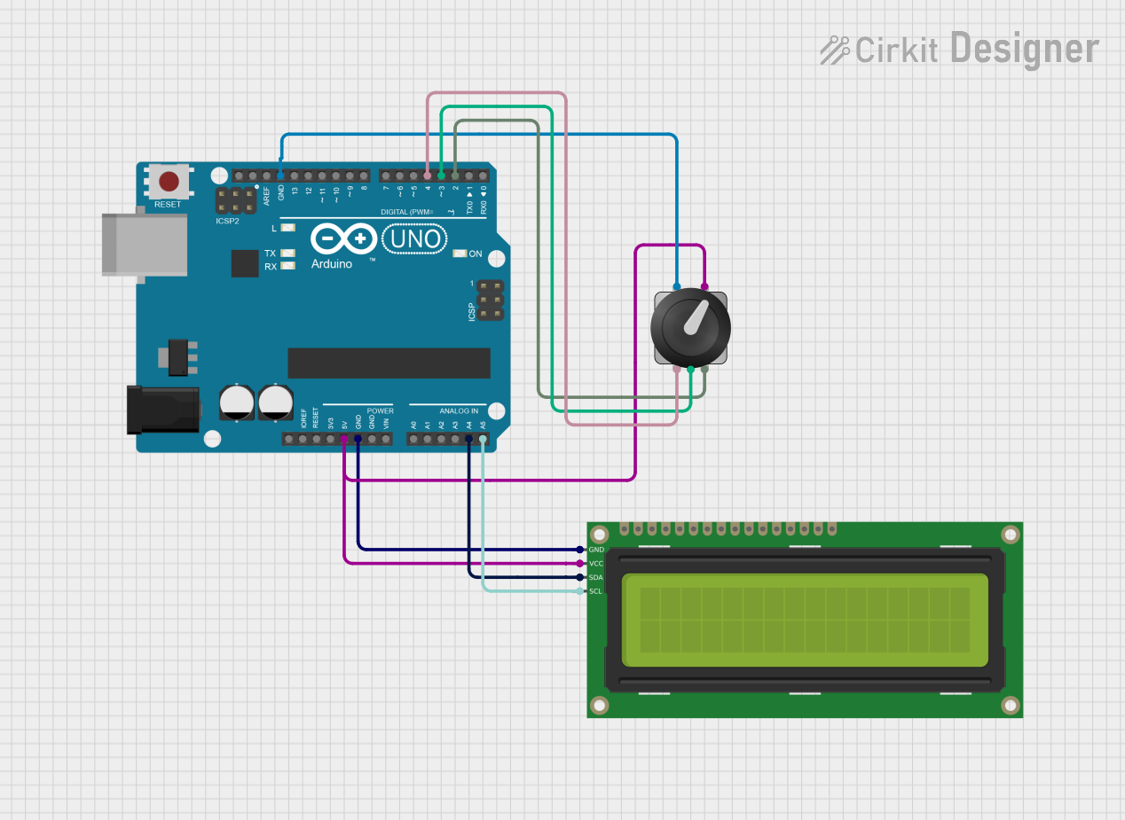
Circuit Documentation
Summary
This circuit is designed for volume control using a rotary encoder and a 16x2 I2C LCD. The rotary encoder allows the user to adjust the volume level between 0 and 100, starting at 50. The current volume level and the state of the button on the rotary encoder are displayed on the LCD. The circuit utilizes an Arduino UNO as the microcontroller to read inputs from the rotary encoder and control the LCD display.
Component List
Arduino UNO
- Description: A microcontroller board based on the ATmega328P. It is used to read inputs from the rotary encoder and control the LCD.
- Purpose: Acts as the central processing unit for the circuit, handling input and output operations.
16x2 I2C LCD
- Description: A liquid crystal display that can show 2 lines of 16 characters each. It communicates with the Arduino via I2C protocol.
- Purpose: Displays the current volume level and the state of the rotary encoder's button.
Rotary Encoder with Knob - Simulate
- Description: A rotary encoder that provides a way to input data by rotating a knob. It has a switch that can be pressed.
- Purpose: Allows the user to adjust the volume and provides a button press input.
Wiring Details
Arduino UNO
5V: Connected to the VCC pin of the 16x2 I2C LCD and the VCC pin of the Rotary Encoder.
GND: Connected to the GND pin of the 16x2 I2C LCD and the GND pin of the Rotary Encoder.
A4 (SDA): Connected to the SDA pin of the 16x2 I2C LCD.
A5 (SCL): Connected to the SCL pin of the 16x2 I2C LCD.
D4: Connected to the SW pin of the Rotary Encoder.
D3: Connected to the DT pin of the Rotary Encoder.
D2: Connected to the CLK pin of the Rotary Encoder.
Documented Code
/*
 * Arduino Sketch for Volume Control using a Rotary Encoder and 16x2 I2C LCD
 *
 * This code reads input from a rotary encoder to adjust a volume level between
 * 0 and 100, starting at 50. The current volume and button state are displayed
 * on a 16x2 I2C LCD. The rotary encoder's CLK and DT pins are connected to
 * digital pins D2 and D3, respectively, and the SW pin is connected to D4.
 * The LCD is connected via I2C to pins A4 (SDA) and A5 (SCL).
 *
 * Clockwise rotation of the encoder increases the volume, while counter-
 * clockwise rotation decreases it. The button press is also detected and
 * displayed on the LCD.
 */

#include <Wire.h>
#include <LiquidCrystal_I2C.h>

// Rotary Encoder Pins
const int clkPin = 2;
const int dtPin = 3;
const int swPin = 4;

// LCD Address and Dimensions
LiquidCrystal_I2C lcd(0x27, 16, 2);

// Volume Control Variables
int volume = 50;
int lastClkState;
bool buttonPressed = false;

void setup() {
  // Initialize Serial Monitor
  Serial.begin(9600);

  // Initialize LCD
  lcd.begin(16,2);
  lcd.backlight();

  // Initialize Rotary Encoder Pins
  pinMode(clkPin, INPUT);
  pinMode(dtPin, INPUT);
  pinMode(swPin, INPUT_PULLUP);

  // Read initial state of CLK
  lastClkState = digitalRead(clkPin);

  // Display initial volume
  updateDisplay();
}

void loop() {
  // Read current state of CLK
  int currentClkState = digitalRead(clkPin);

  // Check for rotation
  if (currentClkState != lastClkState) {
    if (digitalRead(dtPin) == currentClkState) {
      // Clockwise rotation
      if (volume < 100) volume++;
    } else {
      // Counter-clockwise rotation
      if (volume > 0) volume--;
    }
    updateDisplay();
  }
  lastClkState = currentClkState;

  // Check button state
  if (digitalRead(swPin) == LOW) {
    if (!buttonPressed) {
      buttonPressed = true;
      updateDisplay();
    }
  } else {
    if (buttonPressed) {
      buttonPressed = false;
      updateDisplay();
    }
  }
}

void updateDisplay() {
  lcd.clear();
  lcd.setCursor(0, 0);
  lcd.print("Volume: ");
  lcd.print(volume);
  lcd.setCursor(0, 1);
  lcd.print("Button: ");
  lcd.print(buttonPressed ? "Pressed" : "Released");
}
This documentation provides a comprehensive overview of the circuit, detailing the components used, their connections, and the code that drives the functionality of the system.