
ESP32-Based Battery-Powered Motor Control with I2C LCD and LED Indicators
View and Edit Project In Cirkit Designer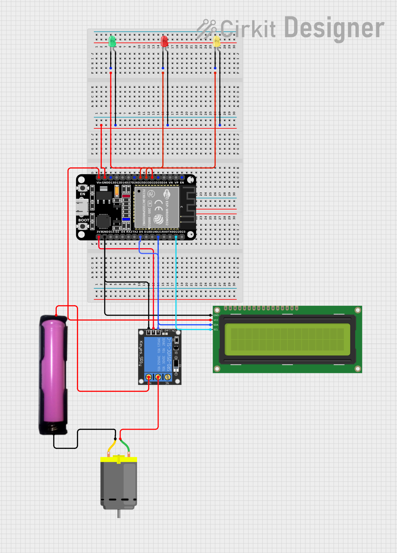
Circuit Documentation
Summary
This circuit involves an ESP32 microcontroller interfacing with various components including LEDs, a relay, a DC motor, an LCD display, and a battery holder. The ESP32 controls the LEDs, relay, and LCD display, while the relay is used to control the DC motor. The circuit is powered by a 18650 battery.
Component List
ESP32 (30 pin)
- Description: A powerful microcontroller with built-in Wi-Fi and Bluetooth capabilities.
- Pins: EN, VP, VN, D34, D35, D32, D33, D25, D26, D27, D14, D12, D13, GND, Vin, D23, D22, TX0, RX0, D21, D19, D18, D5, TX2, RX2, D4, D2, D15, 3V3
1-Channel Relay (5V 10A)
- Description: A relay module used to control high-power devices.
- Pins: NC, signal, C, power, NO, ground
DC Motor
- Description: A simple DC motor.
- Pins: pin 1, pin 2
18650 in holder
- Description: A battery holder for a 18650 lithium-ion battery.
- Pins: GND, VCC
16x2 I2C LCD
- Description: A 16x2 character LCD display with I2C interface.
- Pins: GND, VCC, SDA, SCL
LED: Two Pin (red)
- Description: A red LED.
- Pins: cathode, anode
LED: Two Pin (green)
- Description: A green LED.
- Pins: cathode, anode
LED: Two Pin (yellow)
- Description: A yellow LED.
- Pins: cathode, anode
Wiring Details
ESP32 (30 pin)
- D32: Connected to the cathode of the green LED.
- D33: Connected to the cathode of the red LED.
- D25: Connected to the cathode of the yellow LED.
- GND: Connected to the anodes of the red, green, and yellow LEDs.
- Vin: Connected to VCC of the 16x2 I2C LCD.
- D22: Connected to SCL of the 16x2 I2C LCD.
- D21: Connected to SDA of the 16x2 I2C LCD.
- D5: Connected to the signal pin of the 1-Channel Relay.
- GND: Connected to GND of the 16x2 I2C LCD and ground of the 1-Channel Relay.
- 3V3: Connected to the power pin of the 1-Channel Relay.
1-Channel Relay (5V 10A)
- signal: Connected to D5 of the ESP32.
- ground: Connected to GND of the ESP32.
- power: Connected to 3V3 of the ESP32.
- C: Connected to pin 1 of the DC Motor.
- NO: Connected to VCC of the 18650 in holder.
DC Motor
- pin 1: Connected to C of the 1-Channel Relay.
- pin 2: Connected to GND of the 18650 in holder.
18650 in holder
- VCC: Connected to NO of the 1-Channel Relay.
- GND: Connected to pin 2 of the DC Motor.
16x2 I2C LCD
- VCC: Connected to Vin of the ESP32.
- SCL: Connected to D22 of the ESP32.
- SDA: Connected to D21 of the ESP32.
- GND: Connected to GND of the ESP32 and ground of the 1-Channel Relay.
LED: Two Pin (red)
- cathode: Connected to D33 of the ESP32.
- anode: Connected to GND of the ESP32.
LED: Two Pin (green)
- cathode: Connected to D32 of the ESP32.
- anode: Connected to GND of the ESP32.
LED: Two Pin (yellow)
- cathode: Connected to D25 of the ESP32.
- anode: Connected to GND of the ESP32.
Code
No code is provided for this circuit.