Arduino-Controlled Obstacle Avoiding Robot with Ultrasonic Sensor and IR Detection
Circuit Documentation
Summary
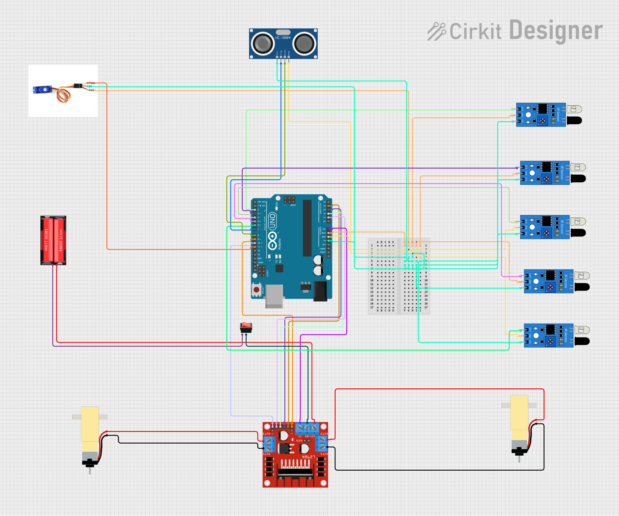
This circuit is designed to interface an Arduino UNO with various sensors and actuators, including IR sensors, an ultrasonic sensor (HC-SR04), a DC motor driver (L298N), hobby gearmotors, a servo motor (SG90), a rocker switch, and a Li-Ion battery (18650). The Arduino UNO controls the motors through the motor driver, reads distance measurements from the ultrasonic sensor, and detects object presence with IR sensors. The servo motor is controlled directly by the Arduino. Power management is handled through the battery, motor driver, and a rocker switch.
Component List
Microcontroller
- Arduino UNO: A microcontroller board based on the ATmega328P, with a variety of digital and analog I/O pins.
Sensors
- HC-SR04 Ultrasonic Sensor: Used for measuring distances via ultrasonic waves.
- IR Sensors: Used for object detection and line tracking.
Actuators
- L298N DC Motor Driver: An H-bridge motor driver that allows for the control of two DC motors.
- Hobby Gearmotors with 48:1 Gearbox: DC motors used for driving wheels or other mechanical parts.
- SG90 Servo Motor: A small and lightweight servo motor for precise angular control.
Power Components
- 18650 Li-Ion Battery: A rechargeable battery providing power to the circuit.
- Rocker Switch: A switch used to control the power flow in the circuit.
Wiring Details
Arduino UNO
- GND: Connected to the ground pins of all IR sensors, the SG90 servo motor, and the HC-SR04 ultrasonic sensor.
- 5V: Powers the IR sensors, the SG90 servo motor, and the HC-SR04 ultrasonic sensor.
- Vin: Connected to the 5V input of the L298N motor driver.
- Digital Pins (D2-D8): Connected to the output pins of the IR sensors and the TRIG/ECHO pins of the HC-SR04.
- Digital Pins (D9-D11): Control the ENA, ENB, and PWM pins of the L298N motor driver and the SG90 servo motor.
- Analog Pins (A1-A4): Control the IN1-IN4 pins of the L298N motor driver.
HC-SR04 Ultrasonic Sensor
- VCC: Powered by the Arduino's 5V output.
- TRIG: Connected to Arduino's D7.
- ECHO: Connected to Arduino's D8.
- GND: Connected to Arduino's GND.
IR Sensors
- VCC: Powered by the Arduino's 5V output.
- GND: Connected to Arduino's GND.
- OUT: Connected to Arduino's digital pins D2-D6.
L298N DC Motor Driver
- 12V: Powered by the 18650 Li-Ion battery.
- GND: Connected to the rocker switch output.
- 5V: Powered by the Arduino's Vin.
- ENA/ENB: Controlled by Arduino's D9 and D10.
- IN1-IN4: Controlled by Arduino's A1-A4.
- OUT1-OUT4: Connected to the pins of the hobby gearmotors.
Hobby Gearmotors
- Pin 1 and Pin 2: Connected to the OUT1-OUT4 of the L298N motor driver.
SG90 Servo Motor
- PWM: Controlled by Arduino's D11.
- 5V: Powered by the Arduino's 5V output.
- GND: Connected to Arduino's GND.
Rocker Switch
- Input: Connected to the negative terminal of the 18650 Li-Ion battery.
- Output: Connected to the GND of the L298N motor driver.
18650 Li-Ion Battery
- Positive: Connected to the 12V input of the L298N motor driver.
- Negative: Connected to the input of the rocker switch.
Documented Code
#include <Servo.h>

int pathLength = 0;
int irSensorPin1 = 2;
int irSensorPin2 = 3;
int irSensorPin3 = 4;
int irSensorPin4 = 5;
int irSensorPin5 = 6;
const int trigPin = 7;
const int echoPin = 8;
int ena = 9;
int enb = 10;
int in1 = A1;
int in2 = A2;
int in3 = A3;
int in4 = A4;
Servo myServo;
long duration;
int distance;
int irValue1 = 0;
int irValue2 = 0;
int irValue3 = 0;
int irValue4 = 0;
int irValue5 = 0;
int pos = 0;
char path[30]; // path storing

void setup() {
  pinMode(irSensorPin1, INPUT);
  pinMode(irSensorPin2, INPUT);
  pinMode(irSensorPin3, INPUT);
  pinMode(irSensorPin4, INPUT);
  pinMode(irSensorPin5, INPUT);
  myServo.attach(11);
  pinMode(trigPin, OUTPUT);
  pinMode(echoPin, INPUT);
  Serial.begin(9600);
  pinMode(ena,OUTPUT);
  pinMode(enb,OUTPUT);
  pinMode(in1,OUTPUT);
  pinMode(in2,OUTPUT);
  pinMode(in3,OUTPUT);
  pinMode(in4,OUTPUT);
}

void loop() {
  Serial.println("chal gya kutte");
  irValue1 = digitalRead(irSensorPin1);
  irValue2 = digitalRead(irSensorPin2);
  irValue3 = digitalRead(irSensorPin3);
  irValue4 = digitalRead(irSensorPin4);
  irValue5 = digitalRead(irSensorPin5);

  digitalWrite(trigPin, LOW);
  delayMicroseconds(2);

  // Trigger the sensor by setting the TRIG pin HIGH for 10 microseconds
  digitalWrite(trigPin, HIGH);
  delayMicroseconds(10);
  digitalWrite(trigPin, LOW);

  duration = pulseIn(echoPin, HIGH);

  // Calculate the distance in centimeters
  distance = duration * 0.034 / 2;

  // ... (Code continues with logic for motor control and path tracking)
}

// ... (Additional functions for motor control and path simplification)
Note: The code provided is a partial listing, focusing on setup and main loop structure. It includes pin assignments, sensor readings, and basic motor control logic. The full code would contain additional logic for path tracking, motor control functions, and path simplification algorithms.