
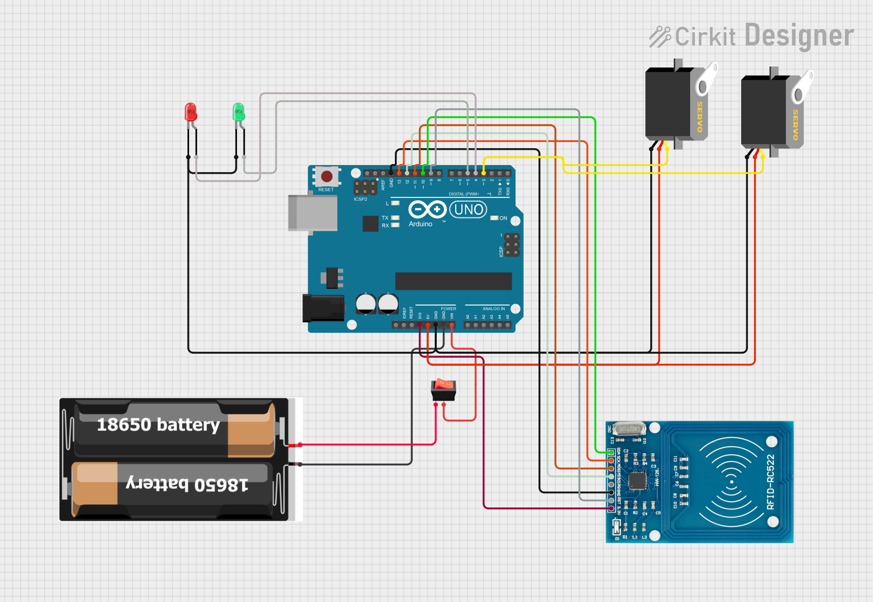
Circuit Documentation
Summary
This document provides a detailed overview of a circuit that includes an Arduino UNO as the central microcontroller, two servo motors, a power source consisting of 2x 18650 batteries, a rocker switch for power control, two LEDs (one green and one red), and an RFID-RC522 module for RFID communication. The Arduino UNO is responsible for controlling the servos and LEDs, as well as interfacing with the RFID module. The circuit is powered by the 18650 batteries, with the rocker switch acting as an on/off control.
Component List
Arduino UNO
- Microcontroller board based on the ATmega328P
- It has 14 digital input/output pins, 6 analog inputs, a 16 MHz quartz crystal, a USB connection, a power jack, an ICSP header, and a reset button.
Servo (x2)
- A rotary actuator or linear actuator that allows for precise control of angular or linear position, velocity, and acceleration.
- It consists of a suitable motor coupled to a sensor for position feedback.
2x 18650 Batteries
- Rechargeable lithium-ion cells
- Commonly used in high-performance electronics.
Rocker Switch
- A switch that rocks back and forth when pressed, which means one side of the switch is raised while the other side is depressed.
- Used to open or close an electrical circuit.
LED: Two Pin (Green)
- A green light-emitting diode that emits light when a current flows through it.
LED: Two Pin (Red)
- A red light-emitting diode that emits light when a current flows through it.
RFID-RC522
- A highly integrated read and write card chip for 13.56MHz contactless communication.
- Used for RFID communication.
Wiring Details
Arduino UNO
3.3Vconnected to RFID-RC522 VCC (3.3V)5Vconnected to both Servo VCC pinsGNDconnected to Servo GND pins, LED cathodes, and RFID-RC522 GNDVinconnected to the rocker switch outputD13connected to RFID-RC522 SCKD12connected to RFID-RC522 MISOD11connected to RFID-RC522 MOSID10connected to RFID-RC522 SDAD9connected to RFID-RC522 RSTD5connected to the anode of the green LEDD4connected to the anode of the red LEDD3connected to the pulse pins of both Servos
Servo Motors
VCCconnected to Arduino UNO 5VGNDconnected to Arduino UNO GNDPulseconnected to Arduino UNO D3
2x 18650 Batteries
VCCconnected to the rocker switch inputGNDconnected to Arduino UNO GND
Rocker Switch
Inputconnected to 2x 18650 VCCOutputconnected to Arduino UNO Vin
LED: Two Pin (Green)
Anodeconnected to Arduino UNO D5Cathodeconnected to Arduino UNO GND
LED: Two Pin (Red)
Anodeconnected to Arduino UNO D4Cathodeconnected to Arduino UNO GND
RFID-RC522
VCC (3.3V)connected to Arduino UNO 3.3VRSTconnected to Arduino UNO D9GNDconnected to Arduino UNO GNDIRQnot connectedMISOconnected to Arduino UNO D12MOSIconnected to Arduino UNO D11SCKconnected to Arduino UNO D13SDAconnected to Arduino UNO D10
Documented Code
Arduino UNO Code (sketch.ino)
void setup() {
  // put your setup code here, to run once:

}

void loop() {
  // put your main code here, to run repeatedly:

}
Note: The provided code is a template and does not include specific functionality. It should be populated with the necessary setup and loop code to control the servos, LEDs, and RFID-RC522 module as required by the circuit's purpose.