
Arduino Mega 2560-Based Temperature and Humidity Monitor with DHT22 Sensor
View and Edit Project In Cirkit Designer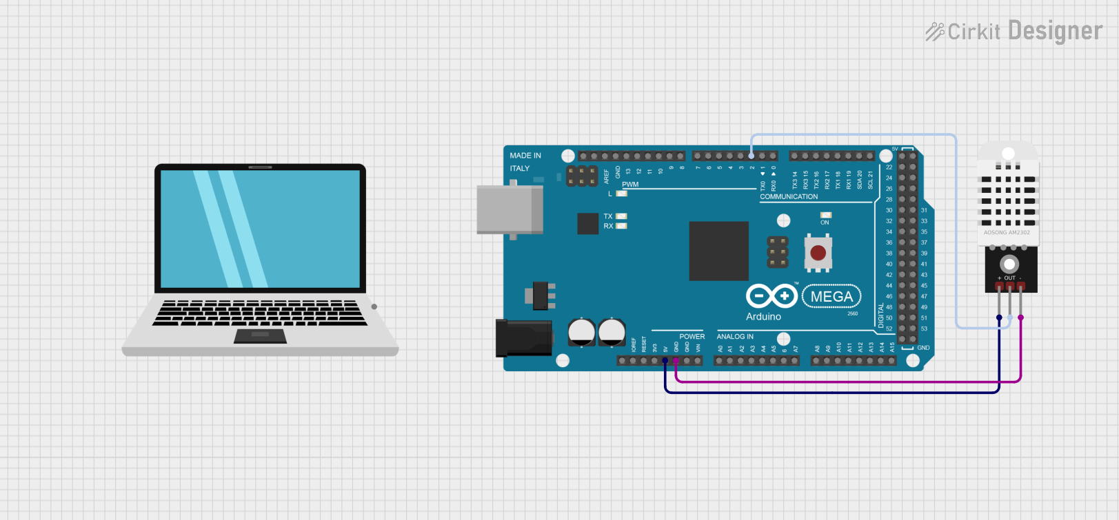
Circuit Documentation
Summary
This document provides a detailed overview of a circuit involving an Arduino Mega 2560 microcontroller and a DHT22 temperature and humidity sensor. The Arduino Mega 2560 is used to read data from the DHT22 sensor. The circuit is powered by the Arduino's 5V output, and the sensor data is read through one of the Arduino's digital PWM pins.
Component List
Arduino Mega 2560
- Description: A microcontroller board based on the ATmega2560.
- Pins: IOREF, RESET, 3V3, 5V, GND, VIN, A0-A15, D21/SCL, D20/SDA, D19/RX1, D18/TX1, D17 PWM/RX2, D16 PWM/TX2, D15/RX3, D14/TX3, D0 RX0, D1 TX0, D2 PWM, D3 PWM, D4 PWM, D5 PWM, D6 PWM, D7 PWM, D8 PWM, D9 PWM, D10 PWM, D11 PWM, D12 PWM, D13 PWM, AREF, SDA, SCL, D52, D50, D48, D46, D44, D42, D40, D38, D36, D34, D32, D30, D28, D26, D24, D22, D53, D51, D49, D47, D45, D43, D41, D39, D37, D35, D33, D31, D29, D27, D25, D23
DHT22
- Description: A digital temperature and humidity sensor.
- Pins: +, Out, -
Laptop
- Description: Used for programming and monitoring the Arduino Mega 2560.
- Pins: pin
Wiring Details
Arduino Mega 2560
- 5V: Connected to the + pin of the DHT22.
- GND: Connected to the - pin of the DHT22.
- D2 PWM: Connected to the Out pin of the DHT22.
DHT22
- +: Connected to the 5V pin of the Arduino Mega 2560.
- -: Connected to the GND pin of the Arduino Mega 2560.
- Out: Connected to the D2 PWM pin of the Arduino Mega 2560.
Documented Code
Arduino Mega 2560 Code
void setup() {
  // put your setup code here, to run once:

}

void loop() {
  // put your main code here, to run repeatedly:

}
This code is a basic template for the Arduino Mega 2560. The setup function is used to initialize any settings or configurations, and the loop function contains the main code that runs repeatedly. In this case, the code is currently empty and needs to be filled in with the logic to read data from the DHT22 sensor and process it as required.