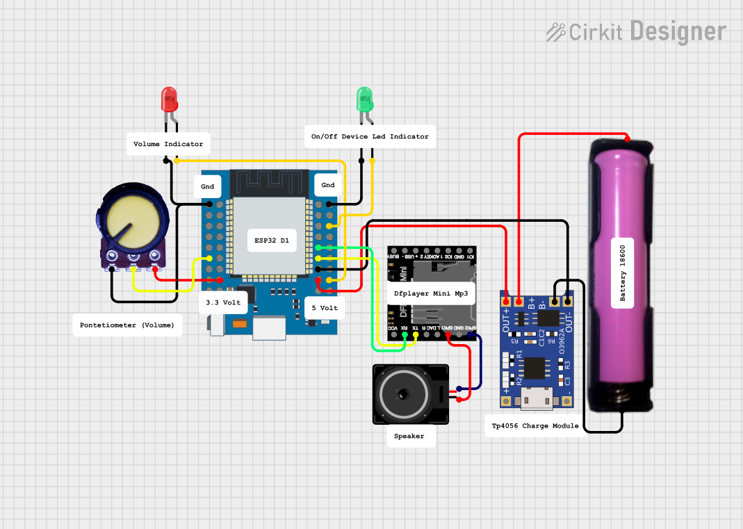
ESP32-Based Audio Player with LED Indicators and Battery Charging

Circuit Documentation
Summary
This circuit integrates an ESP32 Mini microcontroller with a DFPlayer Mini MP3 player module, two LEDs (one green and one red), a loudspeaker, a potentiometer for analog input, and a TP4056 lithium battery charging module with an 18650 battery holder. The ESP32 Mini controls the LEDs and communicates with the DFPlayer Mini to play audio through the loudspeaker. The potentiometer is used to provide analog input to the ESP32 Mini. The TP4056 module is responsible for charging the 18650 battery, which powers the circuit.
Component List
ESP32 Mini
- Microcontroller with WiFi and Bluetooth capabilities.
- It has a variety of GPIO pins for interfacing with other components and peripherals.
DFPlayer Mini
- A compact MP3 player module that can play files from a microSD card or USB stick.
- It has dedicated pins for direct audio output to a speaker.
LED: Two Pin (green)
- A basic green LED with an anode and cathode for indicating statuses such as power or activity.
LED: Two Pin (red)
- A basic red LED similar to the green LED, used for status indication.
Loudspeaker
- An audio output device that plays sound from the DFPlayer Mini.
TP4056
- A lithium battery charging module designed for charging single-cell lithium batteries like the 18650.
18650 in holder
- A rechargeable lithium-ion battery housed in a holder, providing power to the circuit.
Potentiometer
- A three-terminal resistor with an adjustable voltage divider, used for analog input.
Wiring Details
ESP32 Mini
- GND connected to the cathode of the green LED, TP4056 OUT-, Potentiometer GND, and the cathode of the red LED.
- GPIO25 connected to the anode of the green LED.
- GPIO2 connected to the anode of the red LED.
- GPIO17 connected to the RX pin of the DFPlayer Mini.
- GPIO16 connected to the TX pin of the DFPlayer Mini.
- VCC connected to the TP4056 OUT+.
- 3.3V connected to the VCC pin of the Potentiometer.
- GPIO34 connected to the Output pin of the Potentiometer.
DFPlayer Mini
- RX connected to GPIO17 of the ESP32 Mini.
- TX connected to GPIO16 of the ESP32 Mini.
- SPK1 connected to pin1 of the Loudspeaker.
- SPK2 connected to pin2 of the Loudspeaker.
LED: Two Pin (green)
- Cathode connected to GND of the ESP32 Mini.
- Anode connected to GPIO25 of the ESP32 Mini.
LED: Two Pin (red)
- Cathode connected to GND of the ESP32 Mini.
- Anode connected to GPIO2 of the ESP32 Mini.
Loudspeaker
- Pin1 connected to SPK1 of the DFPlayer Mini.
- Pin2 connected to SPK2 of the DFPlayer Mini.
TP4056
- OUT- connected to GND of the ESP32 Mini.
- OUT+ connected to VCC of the ESP32 Mini.
- B- connected to GND of the 18650 in holder.
- B+ connected to VCC of the 18650 in holder.
18650 in holder
- GND connected to B- of the TP4056.
- VCC connected to B+ of the TP4056.
Potentiometer
- GND connected to GND of the ESP32 Mini.
- Output connected to GPIO34 of the ESP32 Mini.
- VCC connected to 3.3V of the ESP32 Mini.
Documented Code
There is no code provided for the microcontroller in this circuit. The ESP32 Mini would typically be programmed to control the DFPlayer Mini, read the potentiometer value, and manage the state of the LEDs based on certain conditions or inputs. Without the code, we cannot document the specific behavior or functionality implemented in the microcontroller.