
Arduino UNO Solar-Powered Smart Lighting System with Motion Detection
View and Edit Project In Cirkit Designer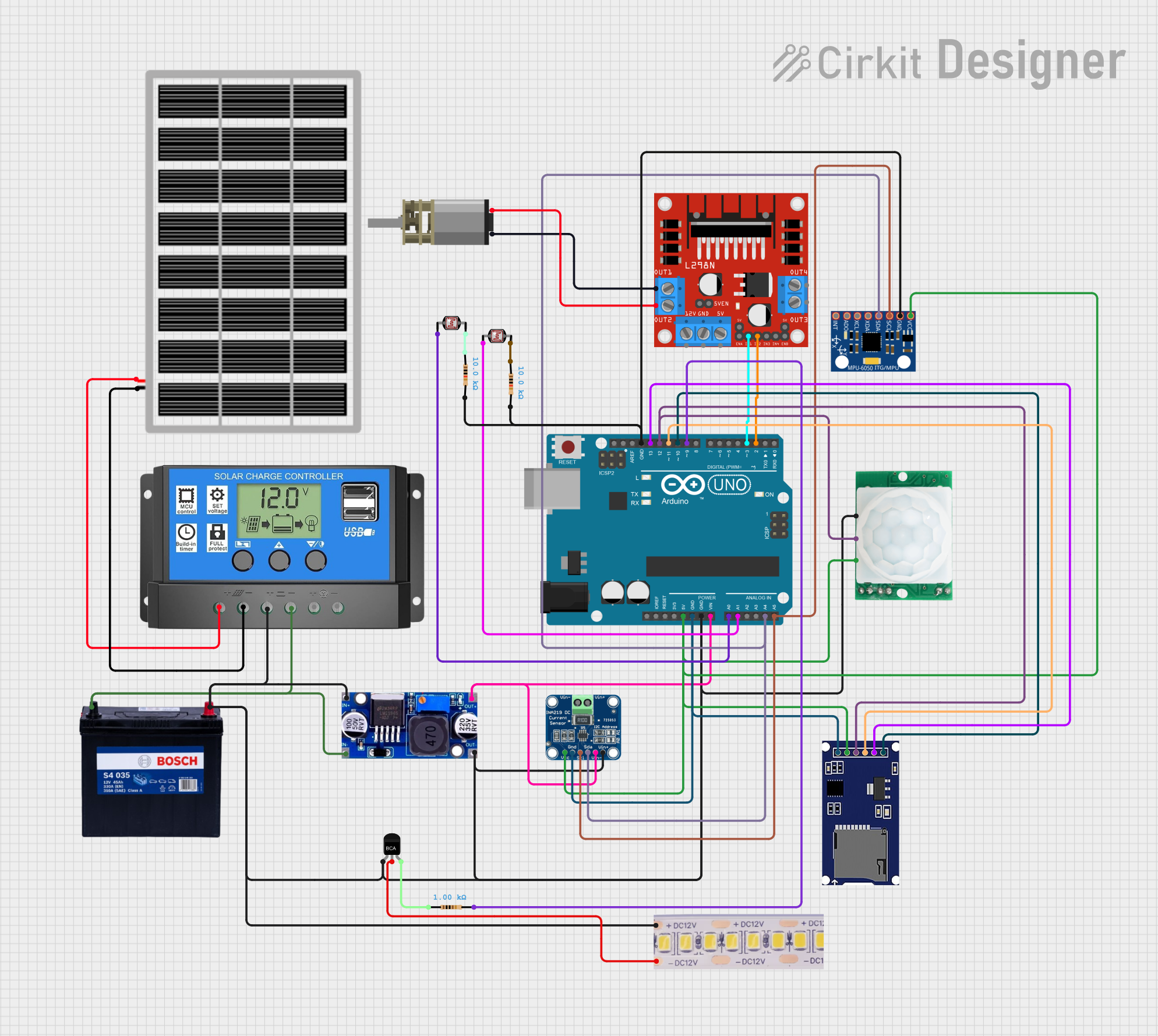
Circuit Documentation
Summary
This circuit is designed to integrate various components including an Arduino UNO, solar panel, solar charge controller, battery, sensors, and other peripherals. The system is powered by a solar panel and a 12V battery, and it includes functionalities for motion detection, light sensing, motor control, and data logging.
Component List
Arduino UNO
- Description: Microcontroller board based on the ATmega328P.
- Pins: UNUSED, IOREF, Reset, 3.3V, 5V, GND, Vin, A0, A1, A2, A3, A4, A5, SCL, SDA, AREF, D13, D12, D11, D10, D9, D8, D7, D6, D5, D4, D3, D2, D1, D0
Solar Panel
- Description: Converts sunlight into electrical energy.
- Pins: gnd, vcc
Solar Charge Controller
- Description: Manages the power from the solar panel to charge the battery.
- Pins: Solar Cell +, Solar Cell -, Battery +, Battery -, Load +, Load -
12V 200Ah Battery
- Description: Stores electrical energy.
- Pins: GND, 12V
LM2596
- Description: DC-DC buck converter.
- Pins: IN, OUT
Photocell (LDR)
- Description: Light-dependent resistor used for light sensing.
- Pins: pin 0, pin 1
INA219
- Description: Current and power monitor.
- Pins: VCC, GND, SCL, SDA, VIN -, VIN +
L298N DC Motor Driver
- Description: Dual H-Bridge motor driver.
- Pins: OUT1, OUT2, 12V, GND, 5V, OUT3, OUT4, 5V-ENA-JMP-I, 5V-ENA-JMP-O, +5V-J1, +5V-J2, ENA, IN1, IN2, IN3, IN4, ENB
DC Mini Metal Gear Motor
- Description: Small DC motor with metal gears.
- Pins: IN1, IN2
Resistor (10k Ohms)
- Description: Resistor with 10k Ohms resistance.
- Pins: pin1, pin2
Resistor (1k Ohms)
- Description: Resistor with 1k Ohms resistance.
- Pins: pin1, pin2
12V White LED Strip
- Description: LED strip powered by 12V.
- Pins: +12V, GND
HC-SR501 Motion Sensor
- Description: PIR motion sensor.
- Pins: GND, OUT, VCC
SD Module
- Description: SD card module for data logging.
- Pins: CS, SCK, MOSI, MISO, VCC, GND
NPN Transistor
- Description: General-purpose NPN transistor.
- Pins: E, C, B
MPU-6050
- Description: 6-axis motion tracking device.
- Pins: VCC, GND, SCL, SDA, XDA, XCL, AD0, INT
Wiring Details
Arduino UNO
- 5V: Connected to VCC of SD Module, HC-SR501 Motion Sensor, MPU-6050, and INA219.
- GND: Connected to GND of SD Module, INA219, HC-SR501 Motion Sensor, MPU-6050, and other components.
- Vin: Connected to OUT of LM2596.
- A0: Connected to pin 0 of Photocell (LDR).
- A1: Connected to pin 0 of another Photocell (LDR).
- A4: Connected to SDA of MPU-6050 and INA219.
- A5: Connected to SCL of MPU-6050 and INA219.
- D13: Connected to SCK of SD Module.
- D12: Connected to MISO of SD Module and OUT of HC-SR501 Motion Sensor.
- D11: Connected to MOSI of SD Module.
- D10: Connected to CS of SD Module.
- D9: Connected to pin2 of 1k Ohm Resistor.
- D3: Connected to IN1 of L298N DC Motor Driver.
- D2: Connected to IN2 of L298N DC Motor Driver.
Solar Panel
- gnd: Connected to Solar Cell - of Solar Charge Controller.
- vcc: Connected to Solar Cell + of Solar Charge Controller.
Solar Charge Controller
- Battery +: Connected to IN of LM2596 and Battery + of 12V 200Ah Battery.
- Battery -: Connected to GND of 12V 200Ah Battery and IN of LM2596.
12V 200Ah Battery
- 12V: Connected to Battery + of Solar Charge Controller and VIN + of INA219.
- GND: Connected to Battery - of Solar Charge Controller and VIN - of INA219.
LM2596
- IN: Connected to Battery + of Solar Charge Controller.
- OUT: Connected to Vin of Arduino UNO and VIN - of INA219.
Photocell (LDR)
- pin 0: Connected to A0 of Arduino UNO.
- pin 1: Connected to pin1 of 10k Ohm Resistor.
INA219
- VCC: Connected to 5V of Arduino UNO.
- GND: Connected to GND of Arduino UNO.
- SCL: Connected to A5 of Arduino UNO.
- SDA: Connected to A4 of Arduino UNO.
- VIN -: Connected to OUT of LM2596.
- VIN +: Connected to 12V of 12V 200Ah Battery.
L298N DC Motor Driver
- IN1: Connected to D3 of Arduino UNO.
- IN2: Connected to D2 of Arduino UNO.
- OUT1: Connected to IN1 of DC Mini Metal Gear Motor.
- OUT2: Connected to IN2 of DC Mini Metal Gear Motor.
DC Mini Metal Gear Motor
- IN1: Connected to OUT1 of L298N DC Motor Driver.
- IN2: Connected to OUT2 of L298N DC Motor Driver.
Resistor (10k Ohms)
- pin1: Connected to pin 1 of Photocell (LDR).
- pin2: Connected to GND of Arduino UNO.
Resistor (1k Ohms)
- pin1: Connected to B of NPN Transistor.
- pin2: Connected to D9 of Arduino UNO.
12V White LED Strip
- +12V: Connected to Battery + of 12V 200Ah Battery.
- GND: Connected to C of NPN Transistor.
HC-SR501 Motion Sensor
- VCC: Connected to 5V of Arduino UNO.
- GND: Connected to GND of Arduino UNO.
- OUT: Connected to D12 of Arduino UNO.
SD Module
- VCC: Connected to 5V of Arduino UNO.
- GND: Connected to GND of Arduino UNO.
- SCK: Connected to D13 of Arduino UNO.
- MISO: Connected to D12 of Arduino UNO.
- MOSI: Connected to D11 of Arduino UNO.
- CS: Connected to D10 of Arduino UNO.
NPN Transistor
- E: Connected to IN of LM2596.
- C: Connected to GND of 12V White LED Strip.
- B: Connected to pin1 of 1k Ohm Resistor.
MPU-6050
- VCC: Connected to 5V of Arduino UNO.
- GND: Connected to GND of Arduino UNO.
- SCL: Connected to A5 of Arduino UNO.
- SDA: Connected to A4 of Arduino UNO.
Documented Code
Arduino UNO Code (sketch.ino)
void setup() {
  // put your setup code here, to run once:

}

void loop() {
  // put your main code here, to run repeatedly:

}
This code is a basic template for the Arduino UNO. The setup() function is used to initialize any settings or configurations, and the loop() function contains the main code that runs repeatedly.