
Circuit Documentation
Summary
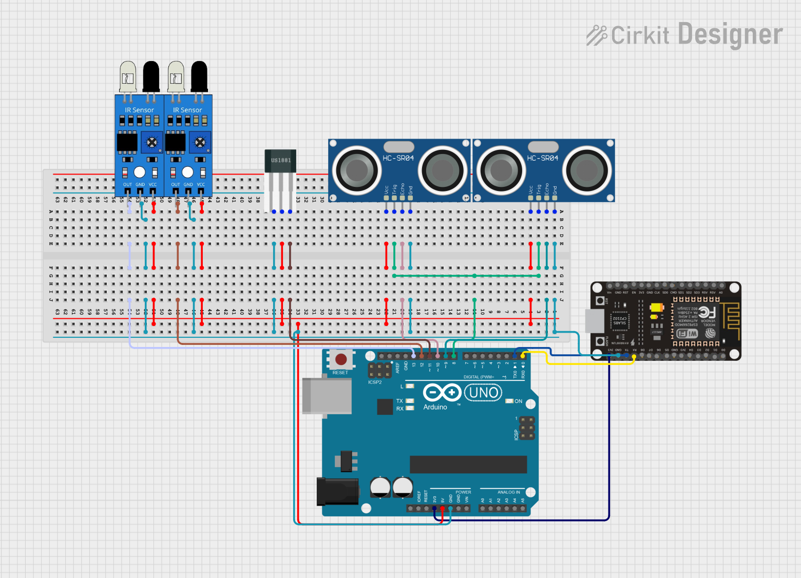
The circuit in question is composed of an Arduino UNO microcontroller, an ESP8266 NodeMCU microcontroller, two IR sensors, two HC-SR04 Ultrasonic Sensors, and a Hall Sensor. The Arduino UNO serves as the primary controller, interfacing with the sensors and the ESP8266 NodeMCU, which can be used for Wi-Fi connectivity. The IR sensors are likely used for detecting objects or motion, while the ultrasonic sensors are used for measuring distances. The Hall Sensor is typically used for detecting magnetic fields.
Component List
Arduino UNO
- Microcontroller board based on the ATmega328P
- It has 14 digital input/output pins, 6 analog inputs, a 16 MHz quartz crystal, a USB connection, a power jack, an ICSP header, and a reset button.
ESP8266 NodeMCU
- A low-cost Wi-Fi microchip with full TCP/IP stack and microcontroller capability.
- It offers a complete and self-contained Wi-Fi networking solution.
IR Sensor
- An infrared sensor that can measure infrared light radiating from objects in its field of view.
- Commonly used for proximity or motion detection.
HC-SR04 Ultrasonic Sensor
- An ultrasonic ranging module that provides 2cm to 400cm non-contact measurement functionality.
- Its operation is not affected by sunlight or black material, although acoustically soft materials like cloth can be difficult to detect.
Hall Sensor
- A transducer that varies its output voltage in response to a magnetic field.
- Typically used for proximity switching, positioning, speed detection, and current sensing applications.
Wiring Details
Arduino UNO
- GND connected to the common ground net.
- 5V supplies power to the VCC net of the sensors.
- D9 connected to the ECHO pin of one HC-SR04 Ultrasonic Sensor.
- D8 connected to the TRIG pins of both HC-SR04 Ultrasonic Sensors.
- D10 connected to the ECHO pin of the other HC-SR04 Ultrasonic Sensor.
- D11 connected to the S pin of the Hall Sensor.
- D12 connected to the OUT pin of one IR Sensor.
- D13 connected to the OUT pin of the other IR Sensor.
- 3.3V supplies power to the ESP8266 NodeMCU.
- D1 (TX) connected to the RX pin of the ESP8266 NodeMCU.
- D0 (RX) connected to the TX pin of the ESP8266 NodeMCU.
ESP8266 NodeMCU
- GND connected to the common ground net.
- 3V3 powered by the 3.3V output from the Arduino UNO.
- RX connected to the TX pin of the Arduino UNO.
- TX connected to the RX pin of the Arduino UNO.
IR Sensor
- OUT of one sensor connected to D12 on the Arduino UNO.
- OUT of the other sensor connected to D13 on the Arduino UNO.
- GND connected to the common ground net.
- VCC connected to the 5V power net.
HC-SR04 Ultrasonic Sensor
- TRIG of both sensors connected to D8 on the Arduino UNO.
- ECHO of one sensor connected to D9 on the Arduino UNO.
- ECHO of the other sensor connected to D10 on the Arduino UNO.
- GND connected to the common ground net.
- VCC connected to the 5V power net.
Hall Sensor
- S connected to D11 on the Arduino UNO.
- - connected to the common ground net.
- + connected to the 5V power net.
Documented Code
Arduino UNO Code (sketch.ino)
void setup() {
  // put your setup code here, to run once:

}

void loop() {
  // put your main code here, to run repeatedly:

}
ESP8266 NodeMCU Code
No code provided for the ESP8266 NodeMCU.
This documentation provides an overview of the circuit's components, their connections, and the initial code for the Arduino UNO. Further development of the code is required to implement the desired functionality of the sensors and communication between the Arduino UNO and the ESP8266 NodeMCU.