
Arduino UNO Controlled Linear Actuator and Stepper Motor System with Multiple Pushbuttons
View and Edit Project In Cirkit Designer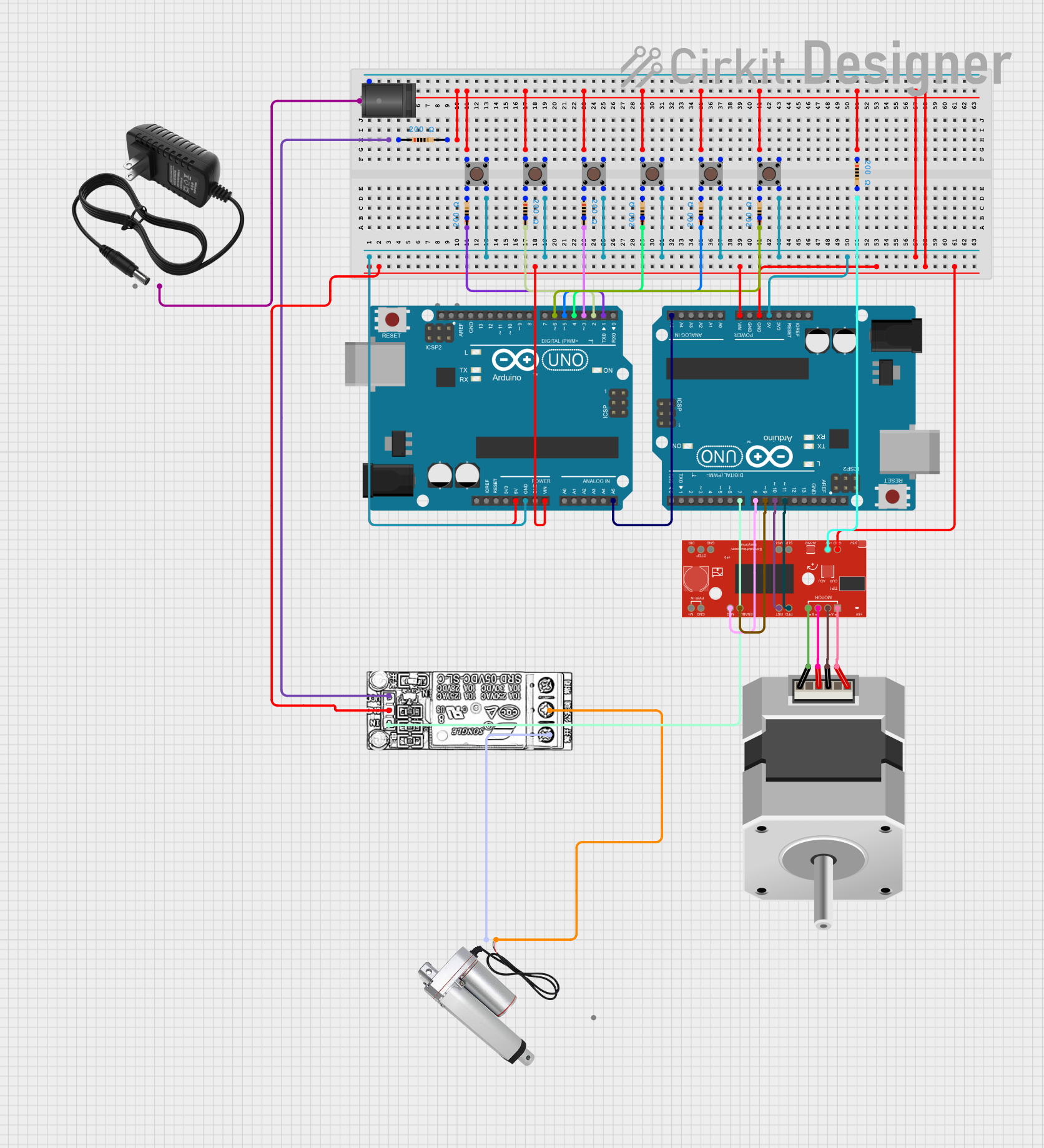
Circuit Documentation
Summary
This circuit involves multiple pushbuttons, resistors, an Arduino UNO, a relay module, a linear actuator, a stepper motor, and an EasyDriver motor driver. The circuit is designed to control the linear actuator and stepper motor using the Arduino UNO, with inputs from various pushbuttons. The power supply is provided by a 12V power source connected through a DC barrel jack.
Component List
12V Power Supply
- Pins: +, -
- Description: Provides 12V power to the circuit.
Pushbutton
- Pins: Pin 1 (in), Pin 2 (in), Pin 3 (out), Pin 4 (out)
- Description: Used for user input to control various functions in the circuit.
Arduino UNO
- Pins: UNUSED, IOREF, Reset, 3.3V, 5V, GND, Vin, A0, A1, A2, A3, A4, A5, SCL, SDA, AREF, D13, D12, D11, D10, D9, D8, D7, D6, D5, D4, D3, D2, D1, D0
- Description: Microcontroller used to control the circuit.
Linear Actuator
- Pins: +, -
- Description: Actuator used for linear motion.
Stepper Motor (Bipolar)
- Pins: A, B, C, D
- Description: Motor used for precise control of angular position.
EasyDriver v4.5
- Pins: GND, V+, STEP, DIR, OUT2A, OUT2B, OUT1A, OUT1B, VCC, MS1, SLEEP, ENABLE, MS2, PFD, RESET
- Description: Motor driver for the stepper motor.
2.1mm DC Barrel Jack
- Pins: switch, sleeve, center
- Description: Connector for the 12V power supply.
Resistor
- Pins: pin1, pin2
- Description: Resistors with 200 Ohms resistance used for current limiting.
Relay Module
- Pins: NC, COM, INPUT, GND, VCC
- Description: Relay used to control the linear actuator.
Wiring Details
12V Power Supply
- + connected to center of 2.1mm DC Barrel Jack
- - connected to sleeve of 2.1mm DC Barrel Jack
Pushbutton
- Pin 1 (in) of multiple pushbuttons connected together and to GND of Arduino UNO
- Pin 2 (in) of each pushbutton connected to:
- D1 of Arduino UNO through a 200 Ohm resistor
- D2 of Arduino UNO through a 200 Ohm resistor
- D3 of Arduino UNO through a 200 Ohm resistor
- D4 of Arduino UNO through a 200 Ohm resistor
- D5 of Arduino UNO through a 200 Ohm resistor
- Pin 3 (out) of one pushbutton connected to D6 of Arduino UNO through a 200 Ohm resistor
- Pin 4 (out) of multiple pushbuttons connected together and to 5V of Arduino UNO
Arduino UNO
- GND connected to GND of Relay Module
- 5V connected to VCC of EasyDriver v4.5
- Vin connected to Vin of another Arduino UNO
- A5 connected to A5 of another Arduino UNO
- D1 connected to Pin 2 (in) of a pushbutton through a 200 Ohm resistor
- D2 connected to Pin 2 (in) of another pushbutton through a 200 Ohm resistor
- D3 connected to Pin 2 (in) of another pushbutton through a 200 Ohm resistor
- D4 connected to Pin 2 (in) of another pushbutton through a 200 Ohm resistor
- D5 connected to Pin 2 (in) of another pushbutton through a 200 Ohm resistor
- D6 connected to Pin 3 (out) of a pushbutton through a 200 Ohm resistor
- D7 connected to INPUT of Relay Module
- D8 connected to MS2 of EasyDriver v4.5
- D9 connected to ENABLE of EasyDriver v4.5
- D10 connected to RESET of EasyDriver v4.5
- D11 connected to PFD of EasyDriver v4.5
Linear Actuator
- + connected to COM of Relay Module
- - connected to NC of Relay Module
Stepper Motor (Bipolar)
- A connected to OUT2A of EasyDriver v4.5
- B connected to OUT1A of EasyDriver v4.5
- C connected to OUT2B of EasyDriver v4.5
- D connected to OUT1B of EasyDriver v4.5
EasyDriver v4.5
- GND connected to GND of Arduino UNO
- VCC connected to 5V of Arduino UNO
- PFD connected to D11 of Arduino UNO
- RESET connected to D10 of Arduino UNO
- ENABLE connected to D9 of Arduino UNO
- MS2 connected to D8 of Arduino UNO
Relay Module
- VCC connected to 5V of Arduino UNO
- GND connected to GND of Arduino UNO
- INPUT connected to D7 of Arduino UNO
- COM connected to + of Linear Actuator
- NC connected to - of Linear Actuator
2.1mm DC Barrel Jack
- sleeve connected to - of 12V Power Supply
- center connected to + of 12V Power Supply
Resistor
- Each resistor (200 Ohms) is connected between the Pin 2 (in) of a pushbutton and the corresponding digital pin (D1, D2, D3, D4, D5, D6) of the Arduino UNO.
Documented Code
Arduino UNO (Instance 1)
void setup() {
  // put your setup code here, to run once:

}

void loop() {
  // put your main code here, to run repeatedly:

}
Arduino UNO (Instance 2)
void setup() {
  // put your setup code here, to run once:

}

void loop() {
  // put your main code here, to run repeatedly:

}
This documentation provides a comprehensive overview of the circuit, including a summary, detailed component list, wiring details, and the code used in the microcontrollers.