Arduino UNO-Based Environmental Monitoring and Alert System with AC Control
Circuit Documentation
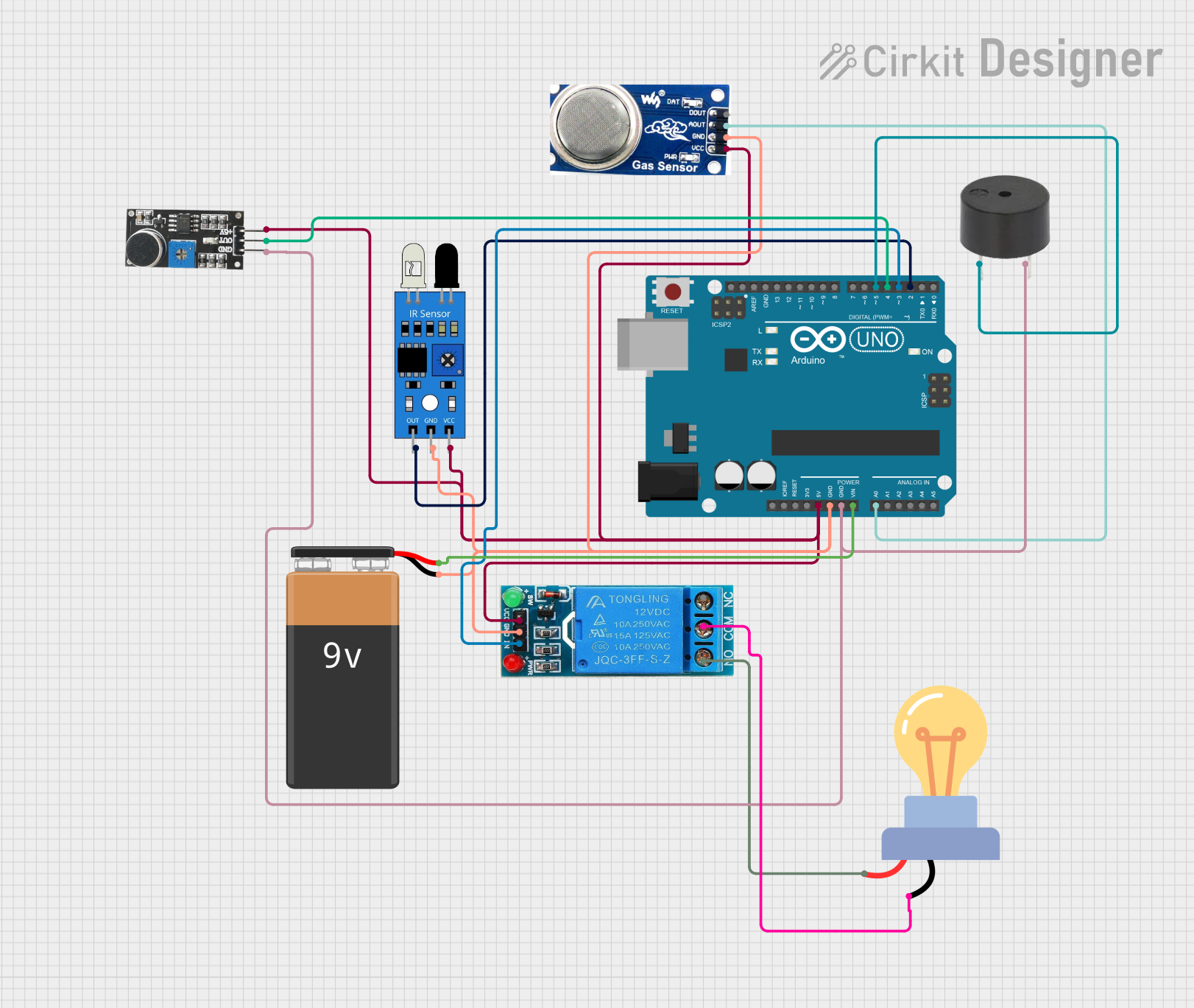
Summary of the Circuit
This circuit is designed to interface an Arduino UNO with various sensors and actuators, including an IR sensor, a smoke sensor, a sound sensor, a single-channel 12V relay, an LED bulb, and a buzzer. The Arduino UNO is powered by a 9V battery and acts as the central processing unit, reading sensor inputs and controlling the output devices based on programmed logic. The relay is used to control the LED bulb, which operates on AC power. The sensors provide environmental feedback to the Arduino, which can trigger the buzzer or the relay based on certain conditions.
Component List
Arduino UNO
- Microcontroller board based on the ATmega328P
- It has 14 digital input/output pins, 6 analog inputs, a 16 MHz quartz crystal, a USB connection, a power jack, an ICSP header, and a reset button.
IR Sensor
- An infrared sensor capable of detecting obstacles and measuring distances.
Smoke Sensor
- A sensor designed to detect smoke particles in the air, which can be indicative of a fire.
12V Single Channel Relay
- An electromechanical switch that allows the Arduino to control higher power circuits, such as an AC bulb.
LED Bulb AC
- An AC-powered light-emitting diode bulb.
Sound Sensor
- A sensor that detects sound levels in the environment, typically used for noise detection.
Buzzer
- An electronic component that produces sound when voltage is applied.
9V Battery
- A standard 9V battery used to power the circuit.
Wiring Details
Arduino UNO
- 5V: Powers the Sound Sensor, IR Sensor, Relay, and Smoke Sensor.
- GND: Common ground for the IR Sensor, Relay, Smoke Sensor, Buzzer, Sound Sensor, and 9V Battery.
- Vin: Connected to the positive terminal of the 9V Battery.
- A0: Receives the analog output from the Smoke Sensor.
- D5: Connected to the Buzzer.
- D4: Connected to the Sound Sensor output.
- D3: Controls the Relay input.
- D2: Reads the output from the IR Sensor.
IR Sensor
- Out: Connected to Arduino UNO D2.
- Gnd: Connected to the common ground.
- Vcc: Powered by the Arduino UNO 5V output.
Smoke Sensor
- DO: Not connected in this circuit.
- AO: Connected to Arduino UNO A0.
- GND: Connected to the common ground.
- VCC: Powered by the Arduino UNO 5V output.
12V Single Channel Relay
- NC: Normally closed terminal, not used in this circuit.
- COM: Connected to the negative terminal of the LED bulb AC.
- NO: Connected to the positive terminal of the LED bulb AC.
- IN: Controlled by Arduino UNO D3.
- GND: Connected to the common ground.
- VCC: Powered by the Arduino UNO 5V output.
LED Bulb AC
- +: Connected to the normally open (NO) terminal of the Relay.
- -: Connected to the common (COM) terminal of the Relay.
Sound Sensor
- 5V +: Powered by the Arduino UNO 5V output.
- OUT: Connected to Arduino UNO D4.
- GND: Connected to the common ground.
Buzzer
- PIN: Connected to Arduino UNO D5.
- GND: Connected to the common ground.
9V Battery
- -: Connected to the common ground.
- +: Connected to Arduino UNO Vin.
Documented Code
Arduino UNO Code (sketch.ino)
void setup() {
  // put your setup code here, to run once:

}

void loop() {
  // put your main code here, to run repeatedly:

}
Note: The provided code is a template and does not contain any functional logic. It needs to be populated with the specific logic required to read sensor inputs and control the outputs based on the desired behavior of the circuit.