
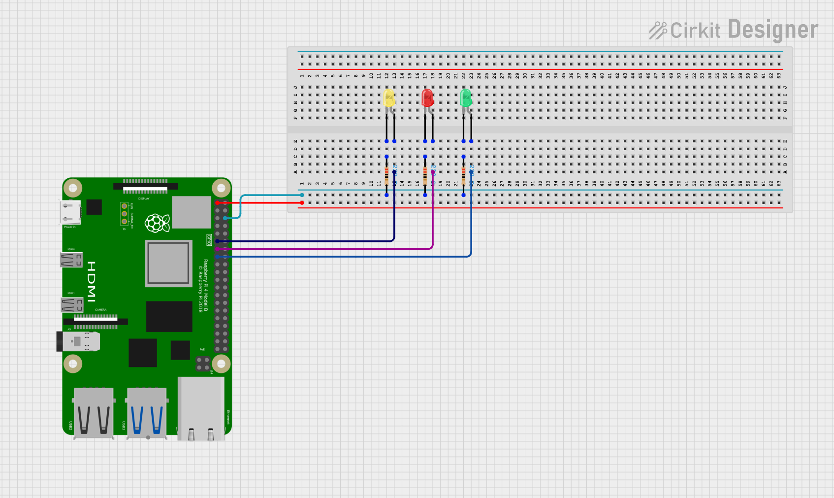
Circuit Documentation
Summary of the Circuit
This circuit is designed to interface with a Raspberry Pi 4B to control three LEDs of different colors: red, green, and yellow. Each LED is connected to a GPIO pin on the Raspberry Pi through a current-limiting resistor to prevent damage to the LEDs. The GPIO pins used are GPIO17, GPIO27, and GPIO22 for the yellow, red, and green LEDs, respectively. The circuit does not include any embedded code for the microcontroller, suggesting that the control logic is to be implemented externally or has not been provided.
Component List
Raspberry Pi 4B
- Description: A single-board computer with multiple GPIO pins for interfacing with various electronic components.
- Pins: 3V3, 5V, multiple GPIOs, GND, and others for different functionalities.
LED: Two Pin (red)
- Description: A red light-emitting diode that emits red light when powered.
- Pins: Anode, Cathode
LED: Two Pin (green)
- Description: A green light-emitting diode that emits green light when powered.
- Pins: Anode, Cathode
LED: Two Pin (yellow)
- Description: A yellow light-emitting diode that emits yellow light when powered.
- Pins: Anode, Cathode
Resistor (220 Ohms)
- Description: A resistor with a resistance of 220 Ohms, used to limit the current through the LEDs.
- Pins: Pin1, Pin2
Wiring Details
Raspberry Pi 4B
- GPIO17 connected to the anode of the yellow LED.
- GPIO27 connected to the anode of the red LED.
- GPIO22 connected to the anode of the green LED.
- GND connected to the second pin (pin2) of all three resistors.
LED: Two Pin (red)
- Anode connected to GPIO27 on the Raspberry Pi 4B.
- Cathode connected to pin1 of a 220 Ohm resistor.
LED: Two Pin (green)
- Anode connected to GPIO22 on the Raspberry Pi 4B.
- Cathode connected to pin1 of a 220 Ohm resistor.
LED: Two Pin (yellow)
- Anode connected to GPIO17 on the Raspberry Pi 4B.
- Cathode connected to pin1 of a 220 Ohm resistor.
Resistor (220 Ohms)
- Pin1 of each resistor is connected to the cathode of each corresponding LED.
- Pin2 of each resistor is connected to the GND pin on the Raspberry Pi 4B.
Documented Code
No code has been provided for the microcontroller (Raspberry Pi 4B) in this circuit. The control logic for the LEDs is expected to be implemented by the user, which would typically involve configuring the GPIO pins as outputs and toggling them to turn the LEDs on and off.