Cirkit Designer
Your all-in-one circuit design IDE
Home /
Project Documentation
Arduino Nano-Based Smart Climate Control System with OLED Display and Rotary Encoder
Circuit Documentation
Summary
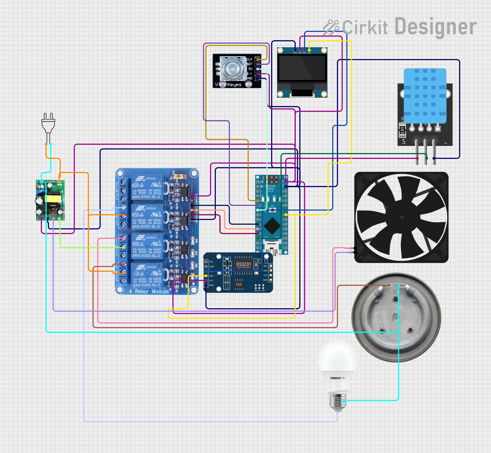
This document provides a detailed overview of a circuit designed to control a heater, fan, and bulb based on temperature and humidity readings. The circuit uses an Arduino Nano microcontroller to interface with various sensors and actuators, including a DHT22 temperature and humidity sensor, a DS3231 RTC module, a 0.96" OLED display, a rotary encoder, and a 4-channel relay module. The system can operate in both automatic and manual modes, with settings adjustable via the rotary encoder.
Component List
Arduino Nano
- Description: Microcontroller board based on the ATmega328P.
- Pins: D1/TX, D0/RX, RESET, GND, D2, D3, D4, D5, D6, D7, D8, D9, D10, D11/MOSI, D12/MISO, VIN, 5V, A7, A6, A5, A4, A3, A2, A1, A0, AREF, 3V3, D13/SCK
Heater Element
- Description: Heating element controlled via relay.
- Pins: VCC, GND
BULB
- Description: Light bulb controlled via relay.
- Pins: +, -
Fan
- Description: Cooling fan controlled via relay.
- Pins: GND, 5V
DS3231 RTC
- Description: Real-time clock module.
- Pins: 32K, SQW, SCL, SDA, VCC, GND
TEMP (DHT22)
- Description: Temperature and humidity sensor.
- Pins: 5V, D3, GND
Relay 4 Channel 5v
- Description: 4-channel relay module for controlling high-power devices.
- Pins: GND, IN1, IN2, IN3, IN4, VCC, COM1, COM2, COM3, COM4, NO1, NO2, NO3, NO4, NC1, NC2, NC3, NC4
0.96" OLED
- Description: OLED display for visual output.
- Pins: GND, VDD, SCK, SDA
Rotary Encoder
- Description: Rotary encoder for user input.
- Pins: clk, dt, sw, gnd, +
AC-DC PSU board 220V-5V&12V
- Description: Power supply unit converting 220V AC to 5V and 12V DC.
- Pins: AC-N, AC-L, +5V, GND, +12V
Power 220v
- Description: 220V AC power source.
- Pins: hot wire, neutral wire
Wiring Details
Arduino Nano
- D2: Connected to Rotary Encoder (clk)
- D3: Connected to Rotary Encoder (dt)
- D4: Connected to Rotary Encoder (sw)
- D7: Connected to Relay 4 Channel 5v (IN3)
- D8: Connected to Relay 4 Channel 5v (IN2)
- D9: Connected to Relay 4 Channel 5v (IN1)
- D10: Connected to TEMP (D3)
- A5: Connected to 0.96" OLED (SCK) and DS3231 RTC (SCL)
- A4: Connected to 0.96" OLED (SDA) and DS3231 RTC (SDA)
- VIN: Connected to +5V from AC-DC PSU board
- GND: Connected to GND from AC-DC PSU board
Heater Element
- VCC: Connected to Relay 4 Channel 5v (NO1)
- GND: Connected to AC-DC PSU board (AC-N) and Power 220v (neutral wire)
BULB
- +: Connected to Relay 4 Channel 5v (NO3)
- -: Connected to AC-DC PSU board (AC-N) and Power 220v (neutral wire)
Fan
- 5V: Connected to Relay 4 Channel 5v (NO2)
- GND: Connected to AC-DC PSU board (GND)
DS3231 RTC
- SCL: Connected to Arduino Nano (A5)
- SDA: Connected to Arduino Nano (A4)
- VCC: Connected to +5V from AC-DC PSU board
- GND: Connected to GND from AC-DC PSU board
TEMP (DHT22)
- D3: Connected to Arduino Nano (D10)
- 5V: Connected to +5V from AC-DC PSU board
- GND: Connected to GND from AC-DC PSU board
Relay 4 Channel 5v
- IN1: Connected to Arduino Nano (D9)
- IN2: Connected to Arduino Nano (D8)
- IN3: Connected to Arduino Nano (D7)
- VCC: Connected to +5V from AC-DC PSU board
- GND: Connected to GND from AC-DC PSU board
- NO1: Connected to Heater Element (VCC)
- NO2: Connected to Fan (5V)
- NO3: Connected to BULB (+)
- COM1: Connected to AC-DC PSU board (AC-L) and Power 220v (hot wire)
- COM2: Connected to +12V from AC-DC PSU board
- COM3: Connected to AC-DC PSU board (AC-L) and Power 220v (hot wire)
0.96" OLED
- SCK: Connected to Arduino Nano (A5)
- SDA: Connected to Arduino Nano (A4)
- VDD: Connected to +5V from AC-DC PSU board
- GND: Connected to GND from AC-DC PSU board
Rotary Encoder
- clk: Connected to Arduino Nano (D2)
- dt: Connected to Arduino Nano (D3)
- sw: Connected to Arduino Nano (D4)
- +: Connected to +5V from AC-DC PSU board
- gnd: Connected to GND from AC-DC PSU board
AC-DC PSU board 220V-5V&12V
- AC-N: Connected to Power 220v (neutral wire)
- AC-L: Connected to Power 220v (hot wire)
- +5V: Connected to Arduino Nano (VIN), Rotary Encoder (+), Relay 4 Channel 5v (VCC), 0.96" OLED (VDD), DS3231 RTC (VCC), TEMP (5V)
- GND: Connected to Arduino Nano (GND), Rotary Encoder (gnd), Relay 4 Channel 5v (GND), 0.96" OLED (GND), DS3231 RTC (GND), TEMP (GND), Fan (GND)
Power 220v
- hot wire: Connected to AC-DC PSU board (AC-L) and Relay 4 Channel 5v (COM1, COM3)
- neutral wire: Connected to AC-DC PSU board (AC-N), Heater Element (GND), BULB (-)
Code Documentation
#include <Wire.h>
#include <RTClib.h>
#include <DHT.h>
#include <Adafruit_GFX.h>
#include <Adafruit_SSD1306.h>
#include <Encoder.h>
#include <EEPROM.h>

#define SCREEN_WIDTH 128
#define SCREEN_HEIGHT 64
#define OLED_RESET -1
Adafruit_SSD1306 display(SCREEN_WIDTH, SCREEN_HEIGHT, &Wire, OLED_RESET);

#define DHTPIN 10 // Pin connected to the DHT sensor
#define DHTTYPE DHT22 // DHT 22 (AM2302)
#define HEATER_PIN 9 // Pin connected to the heater relay
#define FAN_PIN 8 // Pin connected to the fan relay
#define BULB_PIN 7 // Pin connected to the bulb relay

DHT dht(DHTPIN, DHTTYPE);
RTC_DS3231 rtc;
Encoder myEnc(2, 3); // Rotary encoder connected to D2 and D3

int buttonPin = 4; // Rotary encoder button connected to D4
int buttonState = 0;
int lastButtonState = 0;
int dayTemperature = 25; // Default day temperature
int nightTemperature = 15; // Default night temperature
int setHumidity = 40; // Default set humidity threshold
bool manualControl = false; // Flag for manual control
bool heaterState = false;
bool fanState = false;
bool bulbState = false;
enum Mode { SET_DAY_TEMP, SET_NIGHT_TEMP, SET_HUMIDITY, MANUAL_CONTROL };
Mode currentMode = SET_DAY_TEMP;

const int EEPROM_ADDR_DAY_TEMP = 0;
const int EEPROM_ADDR_NIGHT_TEMP =