
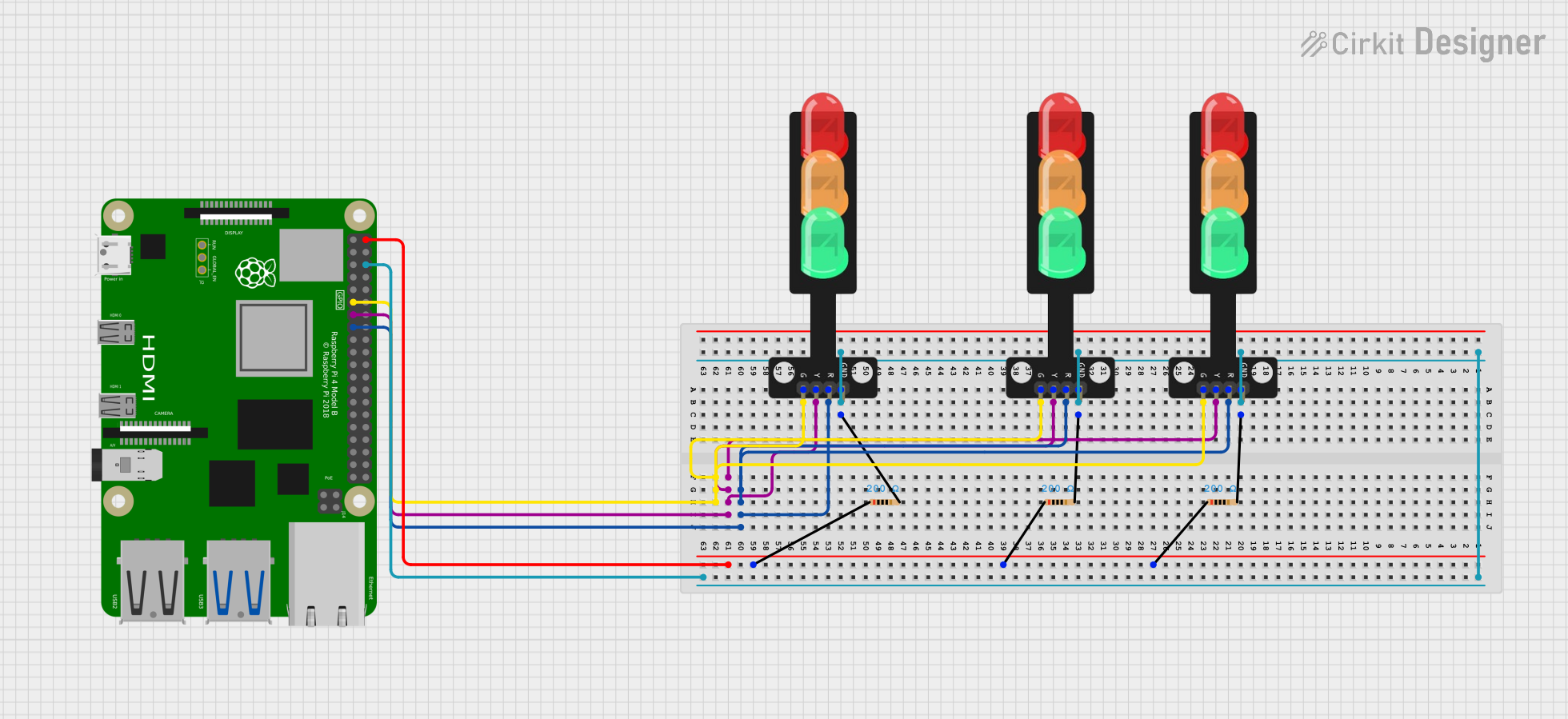
Circuit Documentation
Summary
The circuit in question appears to be designed to control a set of traffic lights using a Raspberry Pi 4B as the central controller. The traffic lights are composed of three individual lights (Red, Yellow, Green) and are connected to the Raspberry Pi via GPIO pins with resistors in series for current limiting. The ground pins of all traffic lights are connected together and to the Raspberry Pi's ground. The circuit does not include any embedded code for the microcontroller, suggesting that the control logic is either not provided or is to be developed separately.
Component List
Raspberry Pi 4B
- Description: A single-board computer with multiple GPIO pins for interfacing with various electronic components.
- Pins: 3V3, 5V, multiple GPIOs, GND, and others for specific functions.
- Purpose: Acts as the central controller for the traffic lights, providing the necessary logic and power signals.
Resistor (200 Ohms)
- Description: A passive two-terminal electrical component that implements electrical resistance as a circuit element.
- Properties: 200 Ohms resistance.
- Purpose: Limits the current flowing to the LEDs of the traffic lights to prevent damage.
Traffic Light
- Description: An electronic representation of a traffic light with Red, Yellow, and Green LEDs.
- Pins: Green, Yellow, Red, GND.
- Purpose: Displays traffic signals controlled by the Raspberry Pi.
Wiring Details
Raspberry Pi 4B
- 5V connected to the anodes of the resistors (pin1).
- GPIO17 connected to the Green pins of all traffic lights.
- GPIO27 connected to the Yellow pins of all traffic lights.
- GPIO22 connected to the Red pins of all traffic lights.
- GND connected to the cathodes of the resistors (pin2) and GND pins of all traffic lights.
Resistor (200 Ohms)
- pin1 connected to the 5V pin of the Raspberry Pi 4B.
- pin2 connected to the GND pins of the traffic lights and the GND pin of the Raspberry Pi 4B.
Traffic Light
- Green connected to GPIO17 of the Raspberry Pi 4B.
- Yellow connected to GPIO27 of the Raspberry Pi 4B.
- Red connected to GPIO22 of the Raspberry Pi 4B.
- GND connected to the cathodes of the resistors (pin2) and the GND pin of the Raspberry Pi 4B.
Documented Code
No code was provided for the microcontroller (Raspberry Pi 4B). The control logic for the traffic lights is expected to be implemented by the user, which would involve setting the GPIO pins to high or low states to turn the corresponding traffic light LEDs on or off.