ESP32-Based Air Quality Monitoring System with Wi-Fi Connectivity and Alerting Features
Circuit Documentation
Summary
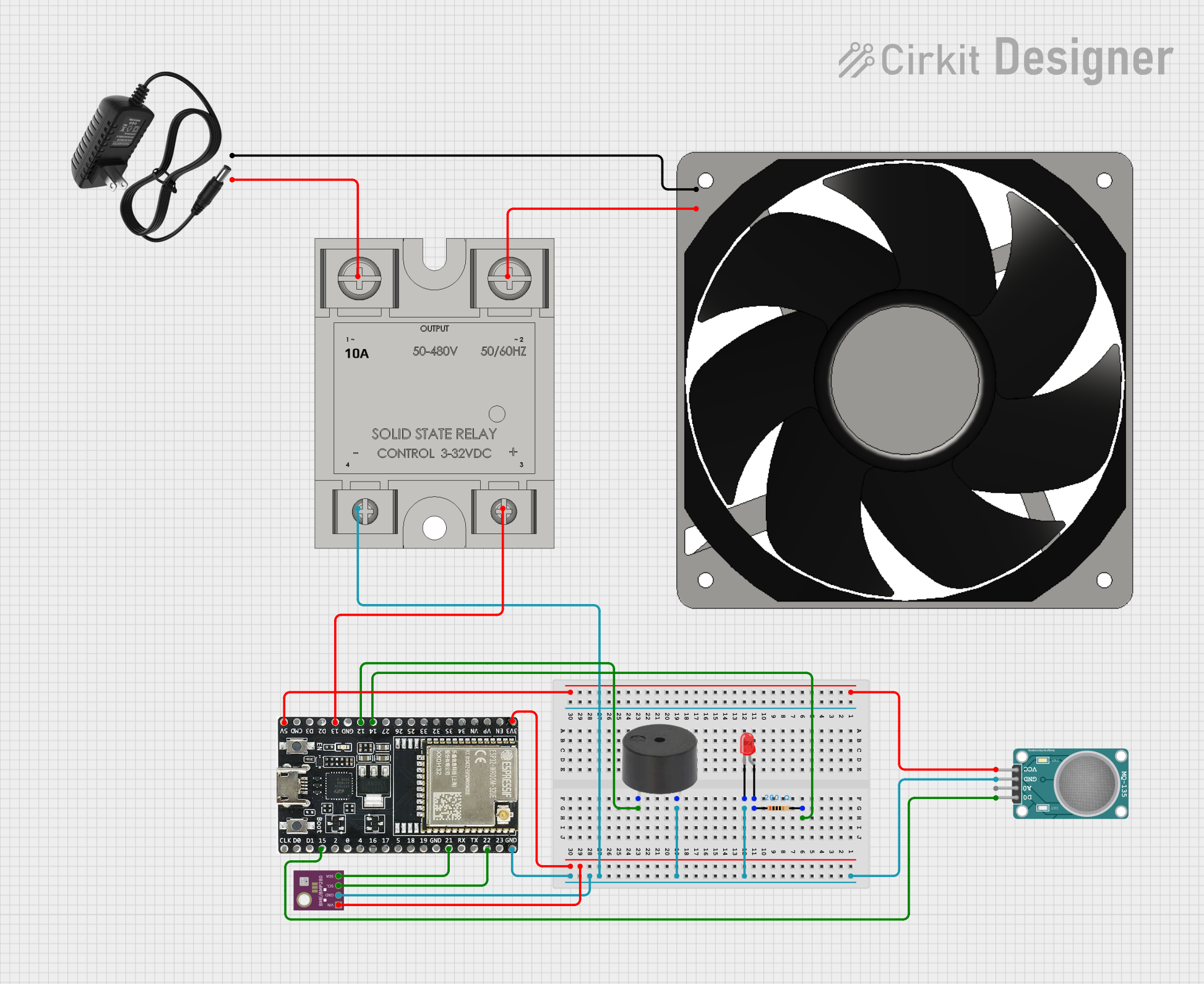
The circuit in question appears to be designed for environmental sensing and control, featuring a microcontroller, air quality sensor, temperature and pressure sensor, a visual and audible alert system, and a power control system for a 12V fan. The ESP32 microcontroller serves as the central processing unit, interfacing with the MQ-135 air quality sensor and the BME/BMP280 temperature and pressure sensor. The LED and buzzer provide visual and audible alerts, respectively. The SSR-10A solid-state relay controls the power to the 12V fan, which is powered by a 12V power supply. A resistor is used in series with the LED to limit current.
Component List
Buzzer
- Description: An audible alert device.
- Pins: PIN, GND
LED: Two Pin (red)
- Description: A visual alert device emitting red light.
- Pins: cathode, anode
MQ-135 SENSOR AIR QUALITY
- Description: A sensor for detecting various gases in the air.
- Pins: VCC, GND, A0, D0
BME/BMP280
- Description: A sensor for measuring temperature, pressure, and humidity.
- Pins: GND, SCL, SDA, VIN
Resistor
- Description: A passive two-terminal electrical component that implements electrical resistance as a circuit element.
- Pins: pin1, pin2
- Properties: Resistance: 200 Ohms
ESP32-WROOM-32UE
- Description: A powerful microcontroller with Wi-Fi and Bluetooth capabilities.
- Pins: 3v3, EN, VP, VN, 34, 35, 32, 33, 25, 26, 27, 14, 12, GND, 13, D2, D3, 5V, 23, 22, TX, RX, 21, 19, 18, 5, 17, 16, 4, 0, 2, 15, D1, D0, CKL
SSR-10A
- Description: A solid-state relay for controlling high power devices.
- Pins: 1-in, 2-out, -, +
120 fan 12v
- Description: A 12V fan for cooling or ventilation.
- Pins: 12V+, GND
12v power supply
- Description: A power supply unit providing 12V DC output.
- Pins: +, -
Wiring Details
Buzzer
- PIN connected to ESP32-WROOM-32UE pin 12
- GND connected to common ground net
LED: Two Pin (red)
- cathode connected to common ground net
- anode connected to one end of the Resistor
MQ-135 SENSOR AIR QUALITY
- VCC connected to ESP32-WROOM-32UE 5V
- GND connected to common ground net
- A0 not connected in the provided net list
- D0 connected to ESP32-WROOM-32UE pin 15
BME/BMP280
- GND connected to common ground net
- SCL connected to ESP32-WROOM-32UE pin 22
- SDA connected to ESP32-WROOM-32UE pin 21
- VIN connected to ESP32-WROOM-32UE 3v3
Resistor
- pin1 connected to LED anode
- pin2 connected to ESP32-WROOM-32UE pin 14
ESP32-WROOM-32UE
- 3v3 connected to BME/BMP280 VIN
- 5V connected to MQ-135 SENSOR AIR QUALITY VCC
- GND connected to common ground net
- 12 connected to Buzzer PIN
- 14 connected to Resistor pin2
- 15 connected to MQ-135 SENSOR AIR QUALITY D0
- 21 connected to BME/BMP280 SDA
- 22 connected to BME/BMP280 SCL
- 13 connected to SSR-10A +
SSR-10A
- 1-in connected to 12v power supply +
- 2-out connected to 120 fan 12v 12V+
- - connected to common ground net
- + connected to ESP32-WROOM-32UE pin 13
120 fan 12v
- 12V+ connected to SSR-10A 2-out
- GND connected to 12v power supply -
12v power supply
- + connected to SSR-10A 1-in
- - connected to 120 fan 12v GND
Documented Code
No code was provided in the input. The ESP32-WROOM-32UE microcontroller would typically be programmed to read sensor data, control the LED and buzzer for alerts, and manage the power to the fan via the SSR-10A based on sensor inputs and possibly other logic. The code would be responsible for initializing the sensors, reading their values, implementing control logic, and handling communication if needed.