
Circuit Documentation
Summary of the Circuit
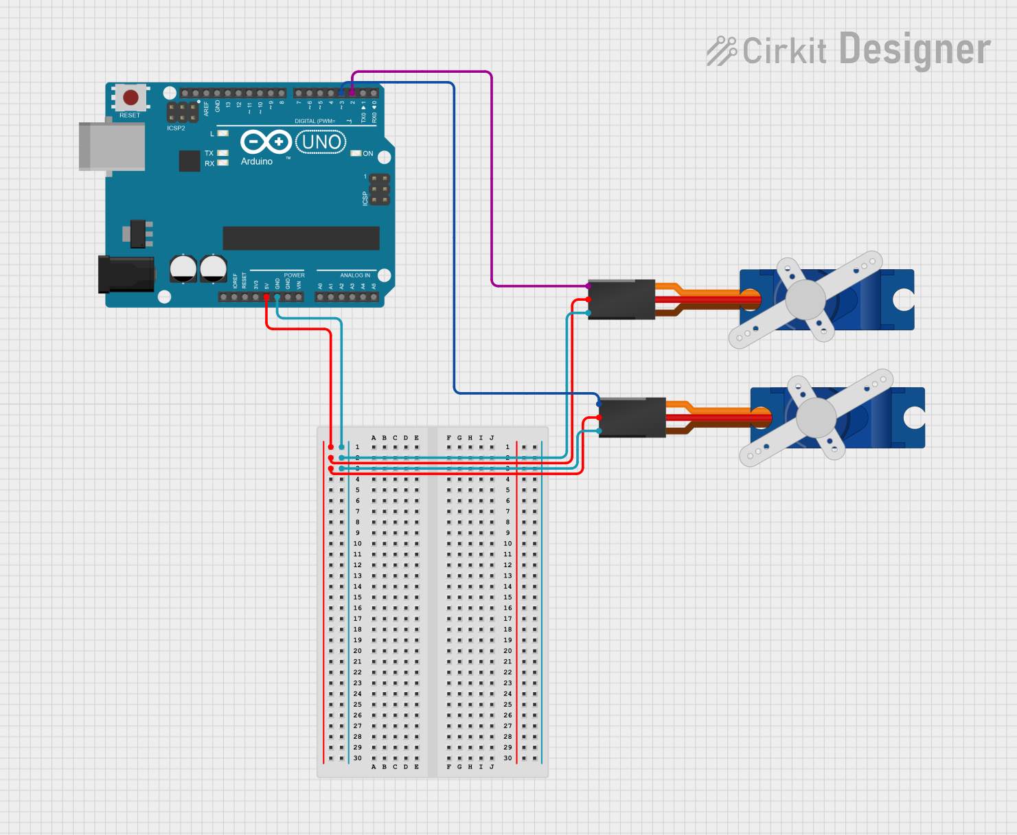
This circuit consists of an Arduino UNO microcontroller board and two Tower Pro SG90 servos. The Arduino UNO is used to control the servos by sending PWM (Pulse Width Modulation) signals to the servos' signal pins. The servos are powered by the 5V output from the Arduino UNO, and all components share a common ground.
Component List
Arduino UNO
- Description: A microcontroller board based on the ATmega328P.
- Pins Used:
5V: Provides power to the servos.GND: Common ground for the circuit.D2: PWM output to control the first servo.D3: PWM output to control the second servo.
Tower Pro SG90 Servo (First Servo)
- Description: A small and lightweight servo motor suitable for RC (Radio Controlled) applications.
- Pins:
Signal: Receives PWM signal for position control.+5V: Power supply input.GND: Ground connection.
Tower Pro SG90 Servo (Second Servo)
- Description: Identical to the first servo, used for additional actuation.
- Pins:
Signal: Receives PWM signal for position control.+5V: Power supply input.GND: Ground connection.
Wiring Details
Arduino UNO
5Vconnected to+5Von both Tower Pro SG90 servos.GNDconnected toGNDon both Tower Pro SG90 servos.D2connected toSignalon the first Tower Pro SG90 servo.D3connected toSignalon the second Tower Pro SG90 servo.
Tower Pro SG90 Servo (First Servo)
Signalconnected toD2on the Arduino UNO.+5Vconnected to5Von the Arduino UNO.GNDconnected toGNDon the Arduino UNO.
Tower Pro SG90 Servo (Second Servo)
Signalconnected toD3on the Arduino UNO.+5Vconnected to5Von the Arduino UNO.GNDconnected toGNDon the Arduino UNO.
Documented Code
The code provided is for the Arduino UNO microcontroller. It is written in Arduino's implementation of C/C++ and is intended to be uploaded to the Arduino UNO using the Arduino IDE or a similar development environment.
sketch.ino
void setup() {
  // put your setup code here, to run once:

}

void loop() {
  // put your main code here, to run repeatedly:

}
This code template includes two main functions: setup() and loop(). The setup() function is called once when the microcontroller is powered on or reset. It is used to initialize the settings, such as pin modes. The loop() function is called repeatedly and contains the main logic of the program.
Currently, the code does not contain any specific instructions for controlling the servos. To control the servos, PWM signals need to be generated on pins D2 and D3 using the analogWrite() function or a servo library that simplifies the control of hobby servos.
documentation.txt
The second code file named documentation.txt is empty and does not contain any code or comments. It is likely intended to be a placeholder for additional documentation or notes related to the codebase.