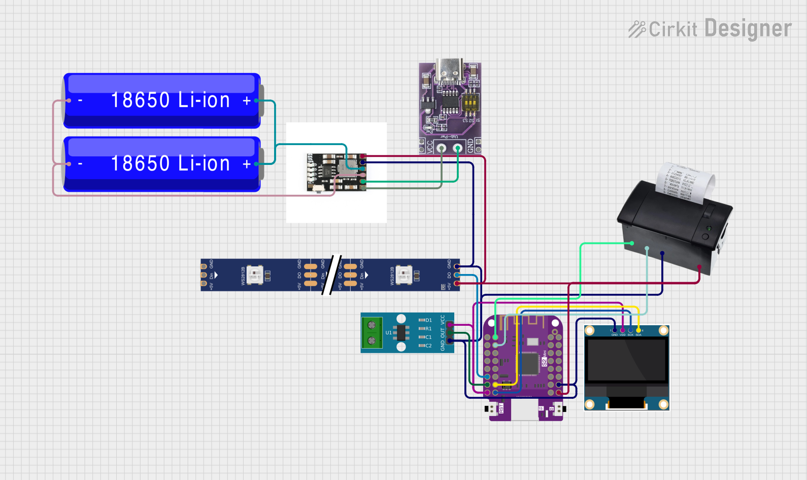
Wemos S2 Mini Controlled Smart Device with OLED Display, Thermal Printing, and RGB LED Strip

Circuit Documentation
Summary
The circuit in question appears to be a multifunctional system that integrates various components including a current sensor, an OLED display, a thermal printer, a USB-C PD trigger board, an RGB LED strip, a battery management system (BMS), and a microcontroller unit (MCU). The system is likely designed for monitoring current, displaying information, controlling an LED strip, and printing receipts or other information. Power management is handled by the BMS and the USB-C PD trigger board, with power supplied by Li-ion batteries.
Component List
ACS712 Current Sensor 5A 20A 30A
- Description: A hall-effect-based linear current sensor capable of measuring both AC and DC currents.
- Pins: 1, 2, GND, OUT, VCC
0.96" OLED
- Description: A small OLED display for visual output.
- Pins: GND, VDD, SCK, SDA
58mm Mini Thermal Printer
- Description: A compact thermal printer for printing receipts or other text-based output.
- Pins: RX, TX, GND, 5-9V
USB-C PD Trigger Board
- Description: A board that enables USB-C power delivery for the circuit.
- Pins: VCC, GND
WS2812 RGB LED Strip
- Description: An addressable LED strip capable of displaying multiple colors.
- Pins: DIN, 5V, GND, DO
18650 Li-ion Battery
- Description: A rechargeable lithium-ion battery commonly used in portable electronics.
- Pins: -, +
CD42 BMS
- Description: A battery management system for charging and protecting Li-ion batteries.
- Pins: OUT 5V, GND, BAT, VIN
Wemos S2 Mini
- Description: A compact MCU with Wi-Fi capabilities based on the ESP32-S2.
- Pins: Multiple GPIOs, 3.3V, VBUS, GND
Wiring Details
ACS712 Current Sensor
- GND: Connected to the common ground.
- OUT: Connected to GPIO 12 on the Wemos S2 Mini.
- VCC: Connected to the 3.3V power rail.
0.96" OLED
- GND: Connected to the common ground.
- VDD: Connected to the 3.3V power rail.
- SCK: Connected to GPIO 14 on the Wemos S2 Mini.
- SDA: Connected to GPIO 13 on the Wemos S2 Mini.
58mm Mini Thermal Printer
- GND: Connected to the common ground.
- RX: Connected to GPIO 1 on the Wemos S2 Mini.
- TX: Connected to GPIO 2 on the Wemos S2 Mini.
- 5-9V: Connected to the VBUS power rail.
USB-C PD Trigger Board
- GND: Connected to the common ground.
- VCC: Connected to the VIN on the CD42 BMS.
WS2812 RGB LED Strip
- GND: Connected to the common ground.
- DIN: Connected to GPIO 11 on the Wemos S2 Mini.
- 5V: Connected to the VBUS power rail.
18650 Li-ion Battery
- -: Connected to the common ground.
- +: Connected to the BAT on the CD42 BMS.
CD42 BMS
- GND: Connected to the common ground.
- OUT 5V: Connected to the VBUS power rail.
- BAT: Connected to the positive terminal of the 18650 Li-ion batteries.
- VIN: Connected to the VCC on the USB-C PD Trigger Board.
Wemos S2 Mini
- GND: Connected to the common ground.
- 3.3V: Connected to the 3.3V power rail.
- VBUS: Connected to the VBUS power rail.
- GPIOs: Connected to various components as detailed above.
Documented Code
No code has been provided for the microcontroller. The functionality of the Wemos S2 Mini within the circuit cannot be documented without the relevant code. Please provide the code for the Wemos S2 Mini to complete this section of the documentation.