Cirkit Designer
Your all-in-one circuit design IDE
Home /
Project Documentation
Arduino Mega 2560 and DRV8825 Stepper Motor Controller with Limit Switch
Circuit Documentation
Summary
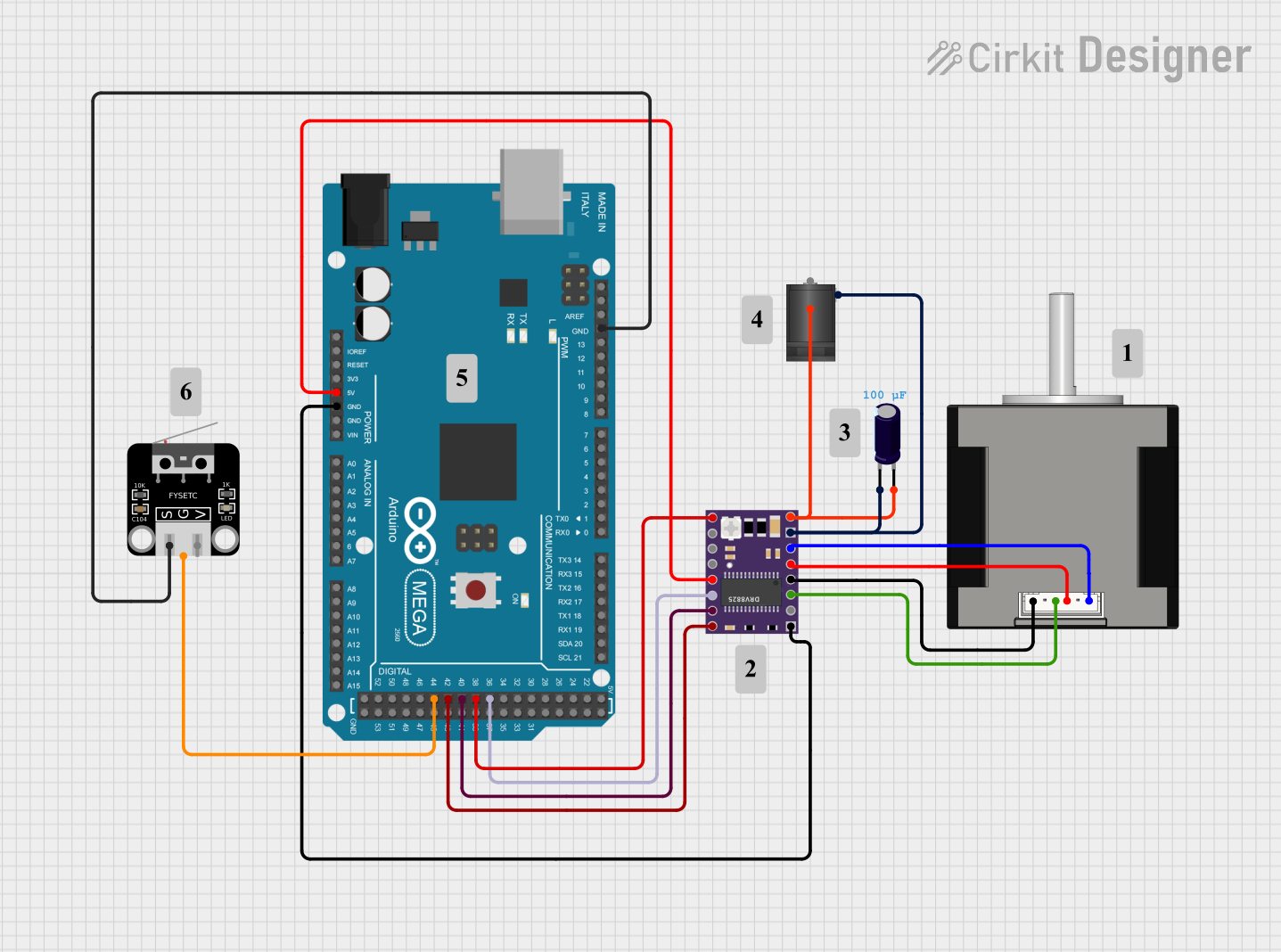
This document provides a detailed overview of a circuit that includes an Arduino Mega 2560 microcontroller, a DRV 8825 stepper motor driver, a Nema 17 stepper motor, a limit switch, an electrolytic capacitor, and a 2.1mm DC barrel jack. The circuit is designed to control the stepper motor using the Arduino, with additional components for power management and input handling.
Component List
DRV 8825
- Description: Stepper motor driver
- Pins: EN, M0, M1, M2, RST, SLP, STEP, DIR, VMOT, GND MOTOR, B2, B1, A1, A2, FAULT, GND LOGIC
2.1mm DC Barrel Jack
- Description: Power input connector
- Pins: switch, sleeve, center
Limit Switch
- Description: Mechanical switch for limit detection
- Pins: S, G, V
Nema 17
- Description: Stepper motor
- Pins: A2(Black), A1 (Green), b1 (red), B2 (blue)
Arduino Mega 2560
- Description: Microcontroller board
- Pins: IOREF, RESET, 3V3, 5V, GND, VIN, A0, A1, A2, A3, A4, A5, A6, A7, A8, A9, A10, A11, A12, A13, A14, A15, D21/SCL, D20/SDA, D19/RX1, D18/TX1, D17 PWM/RX2, D16 PWM/TX2, D15/RX3, D14/TX3, D0 RX0, D1 TX0, D2 PWM, D3 PWM, D4 PWM, D5 PWM, D6 PWM, D7 PWM, D8 PWM, D9 PWM, D10 PWM, D11 PWM, D12 PWM, D13 PWM, AREF, SDA, SCL, D52, D50, D48, D46, D44, D42, D40, D38, D36, D34, D32, D30, D28, D26, D24, D22, D53, D51, D49, D47, D45, D43, D41, D39, D37, D35, D33, D31, D29, D27, D25, D23
Electrolytic Capacitor
- Description: Capacitor for power smoothing
- Pins: -, +
- Properties: Capacitance: 0.0001 Farads
Wiring Details
DRV 8825
- RST connected to 5V of Arduino Mega 2560
- GND LOGIC connected to GND of Arduino Mega 2560
- DIR connected to D42 of Arduino Mega 2560
- STEP connected to D40 of Arduino Mega 2560
- EN connected to D38 of Arduino Mega 2560
- SLP connected to D36 of Arduino Mega 2560
- VMOT connected to + of Electrolytic Capacitor and switch of 2.1mm DC Barrel Jack
- GND MOTOR connected to - of Electrolytic Capacitor and sleeve of 2.1mm DC Barrel Jack
- B2 connected to B2 (blue) of Nema 17
- B1 connected to b1 (red) of Nema 17
- A1 connected to A2(Black) of Nema 17
- A2 connected to A1 (Green) of Nema 17
2.1mm DC Barrel Jack
- switch connected to VMOT of DRV 8825 and + of Electrolytic Capacitor
- sleeve connected to GND MOTOR of DRV 8825 and - of Electrolytic Capacitor
Limit Switch
- S connected to GND of Arduino Mega 2560
- G connected to D44 of Arduino Mega 2560
Nema 17
- B2 (blue) connected to B2 of DRV 8825
- b1 (red) connected to B1 of DRV 8825
- A2(Black) connected to A1 of DRV 8825
- A1 (Green) connected to A2 of DRV 8825
Arduino Mega 2560
- 5V connected to RST of DRV 8825
- GND connected to GND LOGIC of DRV 8825 and S of Limit Switch
- D42 connected to DIR of DRV 8825
- D40 connected to STEP of DRV 8825
- D38 connected to EN of DRV 8825
- D36 connected to SLP of DRV 8825
- D44 connected to G of Limit Switch
Electrolytic Capacitor
- + connected to VMOT of DRV 8825 and switch of 2.1mm DC Barrel Jack
- - connected to GND MOTOR of DRV 8825 and sleeve of 2.1mm DC Barrel Jack
Documented Code
Arduino Mega 2560 Code (sketch.ino)
void setup() {
  // put your setup code here, to run once:

}

void loop() {
  // put your main code here, to run repeatedly:

}
Additional Documentation (documentation.txt)
This document provides a comprehensive overview of the circuit, including the components used, their connections, and the code running on the Arduino Mega 2560.