
Arduino Nano-Based Environmental Monitoring System with DHT11 and MQ-2 Sensors
View and Edit Project In Cirkit Designer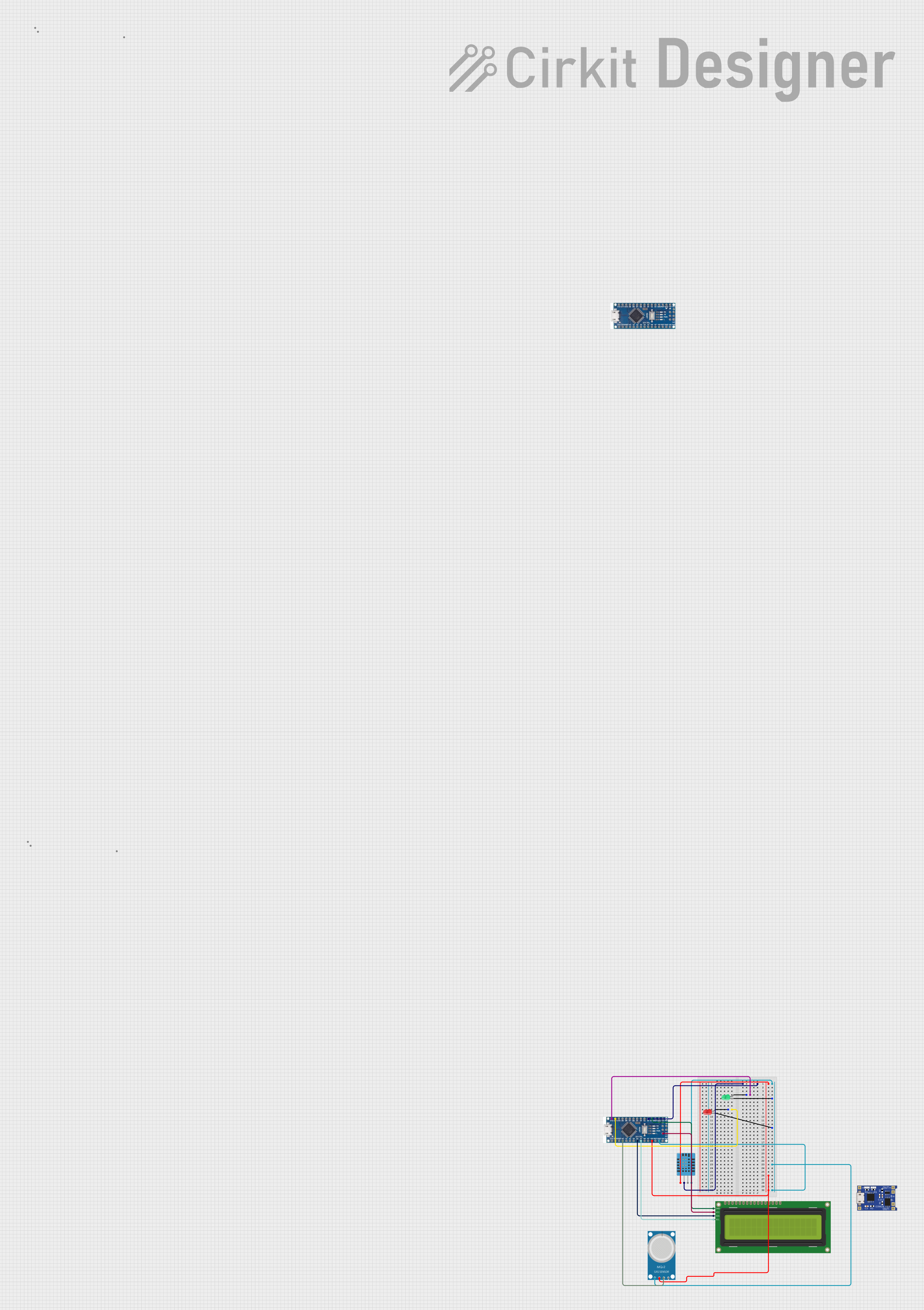
Circuit Documentation
Summary
This circuit involves two Arduino Nano microcontrollers, a DHT11 humidity and temperature sensor, a green LED, a red LED, an MQ-2 gas sensor, a 16x2 I2C LCD, and a TP4056 battery charger. The circuit is designed to read environmental data (temperature, humidity, and gas levels) and display it on the LCD. The LEDs provide visual indicators based on certain conditions.
Component List
Arduino Nano
- Description: A small, complete, and breadboard-friendly board based on the ATmega328P.
- Pins: D12, D11, D10, D9, D8, D7, D6, D5, D4, D3, D2, GND, D13, 3V3, AREF, A0, A1, A2, A3, A4 (SDA), A5 (SCL), A6, A7, 5V, RST, VIN, RX0, TX1, 13, 11, 12
DHT11 Humidity and Temperature Sensor
- Description: A basic, low-cost digital temperature and humidity sensor.
- Pins: VDD, DATA, NULL, GND
LED: Two Pin (red)
- Description: A standard red LED.
- Pins: Cathode, Anode
LED: Two Pin (green)
- Description: A standard green LED.
- Pins: Cathode, Anode
16x2 I2C LCD
- Description: A 16x2 character LCD display with I2C interface.
- Pins: GND, VCC, SDA, SCL
MQ-2 Gas Sensor
- Description: A gas sensor that can detect various gases including LPG, i-butane, propane, methane, alcohol, hydrogen, and smoke.
- Pins: GND, VCC, ANALOG, Digital
TP4056
- Description: A lithium battery charger module.
- Pins: OUT-, B-, B+, OUT+, IN-, IN+
Wiring Details
Arduino Nano (Microcontroller 1)
- D12: Connected to the anode of the green LED.
- D11: Connected to the anode of the red LED.
- D2: Connected to the DATA pin of the DHT11 sensor.
- GND: Connected to the GND pins of the 16x2 I2C LCD, red LED, green LED, DHT11 sensor, and MQ-2 sensor.
- A0: Connected to the ANALOG pin of the MQ-2 sensor.
- A4 (SDA): Connected to the SDA pin of the 16x2 I2C LCD.
- A5 (SCL): Connected to the SCL pin of the 16x2 I2C LCD.
- 5V: Connected to the VCC pins of the DHT11 sensor, MQ-2 sensor, and 16x2 I2C LCD.
Arduino Nano (Microcontroller 2)
- No specific connections detailed in the provided net list.
DHT11 Humidity and Temperature Sensor
- VDD: Connected to the 5V pin of the Arduino Nano.
- DATA: Connected to the D2 pin of the Arduino Nano.
- GND: Connected to the GND pin of the Arduino Nano.
LED: Two Pin (red)
- Anode: Connected to the D11 pin of the Arduino Nano.
- Cathode: Connected to the GND pin of the Arduino Nano.
LED: Two Pin (green)
- Anode: Connected to the D12 pin of the Arduino Nano.
- Cathode: Connected to the GND pin of the Arduino Nano.
16x2 I2C LCD
- GND: Connected to the GND pin of the Arduino Nano.
- VCC: Connected to the 5V pin of the Arduino Nano.
- SDA: Connected to the A4 (SDA) pin of the Arduino Nano.
- SCL: Connected to the A5 (SCL) pin of the Arduino Nano.
MQ-2 Gas Sensor
- GND: Connected to the GND pin of the Arduino Nano.
- VCC: Connected to the 5V pin of the Arduino Nano.
- ANALOG: Connected to the A0 pin of the Arduino Nano.
TP4056
- No specific connections detailed in the provided net list.
Code Documentation
Arduino Nano (Microcontroller 1)
#include <DHT.h>

#define DHTPIN 2     // Pin connected to the DHT sensor
#define DHTTYPE DHT11   // DHT 11

DHT dht(DHTPIN, DHTTYPE);

void setup() {
  Serial.begin(9600);
  dht.begin();
}

void loop() {
  delay(2000); // Wait 2 seconds between measurements
  float humidity = dht.readHumidity();
  float temperature = dht.readTemperature();

  if (isnan(humidity) || isnan(temperature)) {
    Serial.println("Failed to read from DHT sensor!");
    return;
  }

  Serial.print("Humidity: ");
  Serial.print(humidity);
  Serial.print(" %\t");
  Serial.print("Temperature: ");
  Serial.print(temperature);
  Serial.println(" °C");
}
This code initializes the DHT11 sensor and reads the temperature and humidity every 2 seconds. The data is then printed to the serial monitor.