
Arduino Nano-Based GPS and GSM Alert System with Pushbutton Activation
View and Edit Project In Cirkit Designer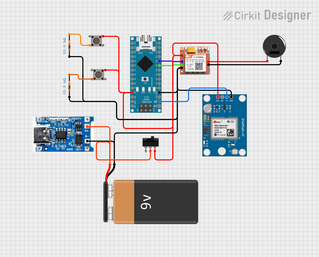
Circuit Documentation
Summary
This circuit is designed to integrate an Arduino Nano with a GPS module, a GSM module, pushbuttons, a piezo buzzer, resistors, a toggle switch, a 9V battery, and a battery charging protection module. The primary function of the circuit is to send an SMS with GPS coordinates or make a call when a button is pressed.
Component List
Arduino Nano
- Description: A small, complete, and breadboard-friendly board based on the ATmega328.
- Pins: D1/TX, D0/RX, RESET, GND, D2, D3, D4, D5, D6, D7, D8, D9, D10, D11/MOSI, D12/MISO, VIN, 5V, A7, A6, A5, A4, A3, A2, A1, A0, AREF, 3V3, D13/SCK
Piezo Buzzer
- Description: A small audio signaling device.
- Pins: pin 1, pin 2
Pushbutton
- Description: A simple pushbutton switch.
- Pins: Pin 3 (out), Pin 4 (out), Pin 1 (in), Pin 2 (in)
Neo 6M GPS Module
- Description: A GPS module for obtaining location data.
- Pins: GND, TX, RX, VCC
Resistor (10k Ohms)
- Description: A resistor with a resistance of 10k Ohms.
- Pins: pin1, pin2
sim 800l
- Description: A GSM module for sending SMS and making calls.
- Pins: NFT, RING, VCC, DTR, RST, MIC +, RXD, MIC-, TXD, SPK+, GND, SPK-
9V Battery
- Description: A 9V battery for powering the circuit.
- Pins: -, +
TP4056 Battery Charging Protection Module (Type C)
- Description: A module for charging and protecting the battery.
- Pins: OUT +, B+, B-, OUT -, +, -
Toggle Switch
- Description: A switch for toggling the power.
- Pins: L1, COM, L2
Wiring Details
Arduino Nano
- D0/RX connected to TX of Neo 6M GPS Module
- GND connected to:
- pin1 of Resistor
- GND of sim 800l
- - of 9V Battery
- B- of TP4056 Battery Charging Protection Module
- GND of Neo 6M GPS Module
- pin1 of another Resistor
- D7 connected to TXD of sim 800l
- D8 connected to RXD of sim 800l
- 5V connected to:
- Pin 1 (in) of Pushbutton
- Pin 1 (in) of another Pushbutton
- VCC of sim 800l
- VCC of Neo 6M GPS Module
- L2 of Toggle Switch
Piezo Buzzer
- pin 1 connected to MIC + of sim 800l
- pin 2 connected to MIC- of sim 800l
Pushbutton
- Pin 4 (out) of one Pushbutton connected to pin2 of Resistor
- Pin 4 (out) of another Pushbutton connected to pin2 of another Resistor
Neo 6M GPS Module
- TX connected to D0/RX of Arduino Nano
- GND connected to GND of Arduino Nano
- VCC connected to 5V of Arduino Nano
Resistor (10k Ohms)
- pin1 connected to GND of Arduino Nano
- pin2 connected to Pin 4 (out) of Pushbutton
sim 800l
- TXD connected to D7 of Arduino Nano
- RXD connected to D8 of Arduino Nano
- VCC connected to 5V of Arduino Nano
- GND connected to GND of Arduino Nano
- MIC + connected to pin 1 of Piezo Buzzer
- MIC- connected to pin 2 of Piezo Buzzer
9V Battery
- - connected to GND of Arduino Nano
- + connected to B+ of TP4056 Battery Charging Protection Module
TP4056 Battery Charging Protection Module (Type C)
- B- connected to GND of Arduino Nano
- B+ connected to + of 9V Battery
Toggle Switch
- COM connected to + of 9V Battery
- L2 connected to 5V of Arduino Nano
Documented Code
//Prateek
//www.justdoelectronics.com

#include <TinyGPS.h>
#include <SoftwareSerial.h>
#include <Wire.h>
SoftwareSerial Gsm(7, 8);
char phone_no[] = "+9188305848xx";  //For SMS
TinyGPS gps;
int state;
String textMessage;

void setup() {
  Serial.begin(9600);
  Gsm.begin(9600);
  delay(2000);

  Serial.print("AT+CMGF=1\r");
  delay(100);
  Serial.print("AT+CNMI=2,2,0,0,0\r");
  delay(100);
  pinMode(4, INPUT);
  pinMode(5, INPUT);
}

void loop() {

  bool newData = false;
  unsigned long chars;
  unsigned short sentences, failed;

  for (unsigned long start = millis(); millis() - start < 1000;) {
    while (Serial.available()) {
      char c = Serial.read();
      Serial.print(c);
      if (gps.encode(c))
        newData = true;
    }
  }
  if (Gsm.available() > 0) {
    textMessage = Gsm.readString();
    textMessage.toUpperCase();
    delay(10);
  }

  state = digitalRead(4);
  if (state == 1)  //When Button is Press
  {
    float flat, flon;
    unsigned long age;
    gps.f_get_position(&flat, &flon, &age);
    Gsm.print("AT+CMGF=1\r");
    delay(400);
    Gsm.print("AT+CMGS=\"");
    Gsm.print(phone_no);
    Gsm.println("\"");
    Gsm.println("Alert I need help.............");
    Gsm.print("http://maps.google.com/maps?q=loc:");
    Gsm.print(flat == TinyGPS::GPS_INVALID_F_ANGLE ? 0.0 : flat, 6);
    Gsm.print(",");
    Gsm.print(flon == TinyGPS ::GPS_INVALID_F_ANGLE ? 0.0 : flon, 6);
    delay(200);
    Gsm.println((char)26);
    delay(200);
    Gsm.println();
    delay(10000);
  } else {
    delay(10);
  }

  state = digitalRead(5);
  if (state == 1)  //When Button is Press
  {

    Serial.println("OK");
    delay(20000);
    Gsm.println("ATD+9188305848xx;");  //For Call
    delay(150000);
    Gsm.println("ATH");
    delay(1000);

  } else {
    delay(10);
  }
  Serial.println(failed);
}
This code initializes the GPS and GSM modules, reads GPS data, and sends an SMS with the GPS coordinates or makes a call when a button is pressed.