Arduino Mega 2560 and ESP32-CAM Sensor Integration for Environmental Monitoring
Circuit Documentation
Summary
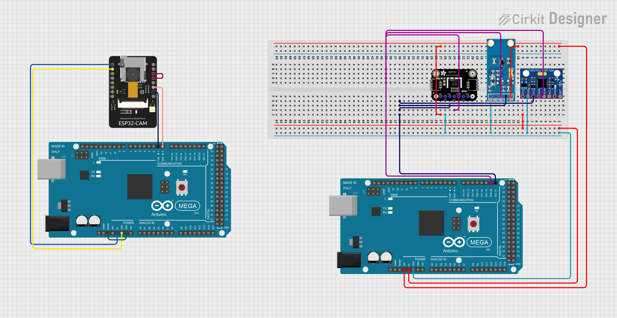
The circuit in question is designed to interface an Arduino Mega 2560 with several sensors and an ESP32-CAM module. The sensors include an Adafruit SHT31-D temperature and humidity sensor, a GY-30 BH1750FVI digital light intensity sensor, and an MPU-6050 accelerometer and gyroscope. The ESP32-CAM is used for camera functionalities and can communicate with the Arduino Mega 2560 via serial communication. The Arduino Mega 2560 also controls an LED connected to pin D13, which blinks in a predefined pattern.
Component List
Arduino Mega 2560
- Microcontroller board based on the ATmega2560
- It has 54 digital input/output pins (of which 15 can be used as PWM outputs), 16 analog inputs, 4 UARTs (hardware serial ports), a 16 MHz crystal oscillator, a USB connection, a power jack, an ICSP header, and a reset button.
ESP32-CAM
- A small camera module with the ESP32-S chip that besides featuring a camera, also includes a microSD card slot, and several GPIOs to connect peripherals.
Adafruit SHT31-D
- A temperature and humidity sensor with a digital interface (I2C), high accuracy, and easy interfacing with microcontrollers.
GY-30 BH1750FVI Digital Light Intensity Illumination Sensor
- A digital light sensor that measures the intensity of light using an I2C interface.
MPU-6050
- A motion-tracking device that combines a 3-axis gyroscope and a 3-axis accelerometer on the same silicon die, along with an onboard Digital Motion Processor™ (DMP™) capable of processing complex 9-axis MotionFusion algorithms.
Wiring Details
Arduino Mega 2560
3V3connected to Adafruit SHT31-D VCC and GY-30 BH1750FVI Vcc (3.3v)5Vconnected to MPU-6050 VCCGNDconnected to MPU-6050 GND, GY-30 BH1750FVI Gnd(-) negative, and Adafruit SHT31-D GNDD21/SCLconnected to Adafruit SHT31-D SCL, MPU-6050 SCL, and GY-30 BH1750FVI SCLD20/SDAconnected to Adafruit SHT31-D SDA, MPU-6050 SDA, and GY-30 BH1750FVI SDAD13used to control an LED (not listed in the parts list)
ESP32-CAM
5Vconnected to the 5V of the second Arduino Mega 2560GNDconnected to the GND of the second Arduino Mega 2560VOTconnected toD1 TX0of the second Arduino Mega 2560VORconnected toD0 RX0of the second Arduino Mega 2560IO0connected to its own GND for programming mode
Adafruit SHT31-D
VCCconnected to 3V3 of Arduino Mega 2560GNDconnected to GND of Arduino Mega 2560SCLconnected to D21/SCL of Arduino Mega 2560SDAconnected to D20/SDA of Arduino Mega 2560
GY-30 BH1750FVI Digital Light Intensity Illumination Sensor
Vcc (3.3v)connected to 3V3 of Arduino Mega 2560Gnd(-) negativeconnected to GND of Arduino Mega 2560SCLconnected to D21/SCL of Arduino Mega 2560SDAconnected to D20/SDA of Arduino Mega 2560
MPU-6050
VCCconnected to 5V of Arduino Mega 2560GNDconnected to GND of Arduino Mega 2560SCLconnected to D21/SCL of Arduino Mega 2560SDAconnected to D20/SDA of Arduino Mega 2560
Documented Code
Arduino Mega 2560 (First Instance)
/*
 * This Arduino Sketch controls an LED connected to pin D13.
 * The LED will turn on for one second, then turn off for two seconds,
 * repeating this cycle indefinitely.
 */

void setup() {
  // Initialize digital pin D13 as an output.
  pinMode(13, OUTPUT);
}

void loop() {
  // Turn the LED on (HIGH is the voltage level)
  digitalWrite(13, HIGH);
  // Wait for one second
  delay(1000);
  // Turn the LED off by making the voltage LOW
  digitalWrite(13, LOW);
  // Wait for two seconds
  delay(2000);
}
Arduino Mega 2560 (Second Instance)
/*
 * This Arduino Sketch is intended for the second Arduino Mega 2560.
 * It is currently identical to the first instance and controls an LED on pin D13.
 * Additional functionality for communication with the ESP32-CAM can be added.
 */

void setup() {
  // Initialize digital pin D13 as an output.
  pinMode(13, OUTPUT);
}

void loop() {
  // Turn the LED on (HIGH is the voltage level)
  digitalWrite(13, HIGH);
  // Wait for one second
  delay(1000);
  // Turn the LED off by making the voltage LOW
  digitalWrite(13, LOW);
  // Wait for two seconds
  delay(2000);
}
This documentation provides an overview of the circuit, including the components used, their wiring, and the code that runs on the microcontrollers. Further details can be added to describe the purpose and functionality of each part within the circuit.