
Arduino UNO-Based Light-Activated Servo Control System with LDR Sensor and Battery Power
View and Edit Project In Cirkit Designer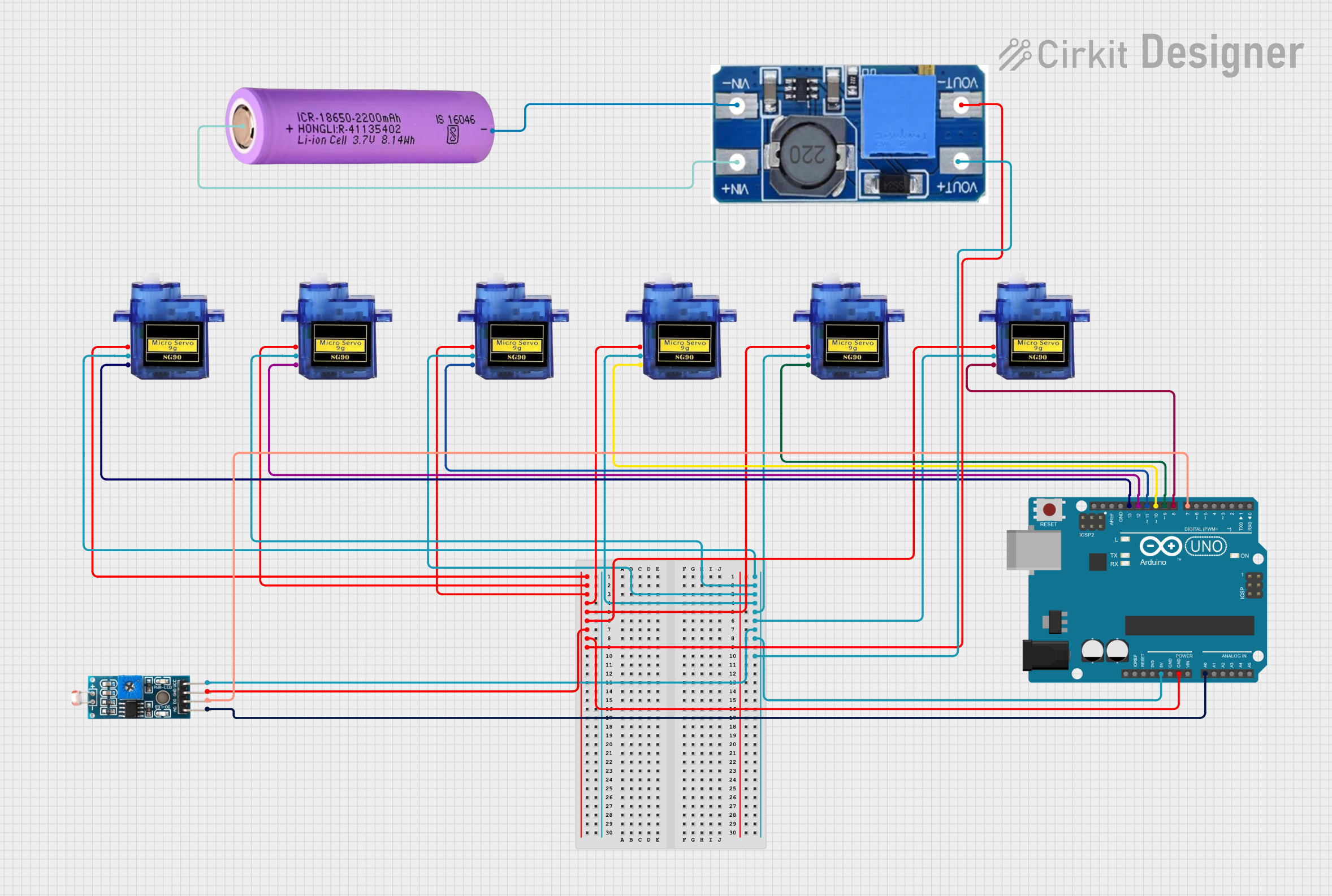
Circuit Documentation
Summary
This circuit is designed to control six servo motors based on the input from an LDR (Light Dependent Resistor) sensor using an Arduino UNO. When the LDR sensor detects light, all six servo motors move to 90 degrees. When the LDR sensor stops detecting light, the servos return to 0 degrees. The circuit is powered by a 18650 battery through a Step Up Boost Power Converter to provide a stable 5V supply.
Component List
Arduino UNO
- Description: Microcontroller board based on the ATmega328P.
- Pins: UNUSED, IOREF, Reset, 3.3V, 5V, GND, Vin, A0, A1, A2, A3, A4, A5, SCL, SDA, AREF, D13, D12, D11, D10, D9, D8, D7, D6, D5, D4, D3, D2, D1, D0
Module LDR
- Description: Light Dependent Resistor module for detecting light intensity.
- Pins: VCC, GND, DO, AO
Micro servo 9G
- Description: Small servo motor for precise control of angular position.
- Pins: GND, +5V, PWM
Battery 18650
- Description: Rechargeable lithium-ion battery.
- Pins: +, -
Step Up Boost Power Converter, Adjustable Voltage Regulator
- Description: Boost converter to step up the voltage from the battery to a stable 5V.
- Pins: VOUT+, VOUT-, VIN+, VIN-
Wiring Details
Arduino UNO
- GND: Connected to GND of all Micro servos, Module LDR, and VOUT- of the Step Up Boost Power Converter.
- 5V: Connected to +5V of all Micro servos, VCC of Module LDR, and VOUT+ of the Step Up Boost Power Converter.
- A0: Connected to AO of Module LDR.
- D13: Connected to PWM of Micro servo 9G.
- D12: Connected to PWM of Micro servo 9G.
- D11: Connected to PWM of Micro servo 9G.
- D10: Connected to PWM of Micro servo 9G.
- D9: Connected to PWM of Micro servo 9G.
- D8: Connected to PWM of Micro servo 9G.
- D7: Connected to DO of Module LDR.
Module LDR
- GND: Connected to GND of Arduino UNO.
- VCC: Connected to 5V of Arduino UNO.
- DO: Connected to D7 of Arduino UNO.
- AO: Connected to A0 of Arduino UNO.
Micro servo 9G
- GND: Connected to GND of Arduino UNO.
- +5V: Connected to 5V of Arduino UNO.
- PWM: Connected to respective digital pins (D13, D12, D11, D10, D9, D8) of Arduino UNO.
Battery 18650
- +: Connected to VIN+ of Step Up Boost Power Converter.
- -: Connected to VIN- of Step Up Boost Power Converter.
Step Up Boost Power Converter, Adjustable Voltage Regulator
- VOUT+: Connected to 5V of Arduino UNO.
- VOUT-: Connected to GND of Arduino UNO.
- VIN+: Connected to + of Battery 18650.
- VIN-: Connected to - of Battery 18650.
Code Documentation
/*
 * This Arduino Sketch controls 6 servo motors based on the input from an LDR sensor.
 * When the LDR sensor detects light, all 6 servo motors move to 90 degrees.
 * When the LDR sensor stops detecting light, the servos return to 0 degrees.
 */

#include <Servo.h>

// Define servo objects
Servo servo1;
Servo servo2;
Servo servo3;
Servo servo4;
Servo servo5;
Servo servo6;

// Define pin connections
const int ldrDigitalPin = 7;
const int ldrAnalogPin = A0;
const int servoPin1 = 13;
const int servoPin2 = 12;
const int servoPin3 = 11;
const int servoPin4 = 10;
const int servoPin5 = 9;
const int servoPin6 = 8;

void setup() {
  // Attach servos to their respective pins
  servo1.attach(servoPin1);
  servo2.attach(servoPin2);
  servo3.attach(servoPin3);
  servo4.attach(servoPin4);
  servo5.attach(servoPin5);
  servo6.attach(servoPin6);

  // Set LDR pin as input
  pinMode(ldrDigitalPin, INPUT);
}

void loop() {
  // Read the digital value from the LDR sensor
  int ldrStatus = digitalRead(ldrDigitalPin);

  if (ldrStatus == HIGH) { // Light detected
    // Move all servos to 90 degrees
    servo1.write(90);
    servo2.write(90);
    servo3.write(90);
    servo4.write(90);
    servo5.write(90);
    servo6.write(90);
  } else { // No light detected
    // Move all servos back to 0 degrees
    servo1.write(0);
    servo2.write(0);
    servo3.write(0);
    servo4.write(0);
    servo5.write(0);
    servo6.write(0);
  }

  // Small delay to avoid bouncing
  delay(100);
}
This code initializes six servo motors and an LDR sensor. In the setup function, the servos are attached to their respective pins, and the LDR pin is set as an input. In the loop function, the code reads the digital value from the LDR sensor. If light is detected, all servos move to 90 degrees. If no light is detected, the servos return to 0 degrees. A small delay is added to avoid bouncing.