
ESP32-Based Smart Alarm Clock with OLED Display, DHT11 Sensor, and Wi-Fi Connectivity
View and Edit Project In Cirkit Designer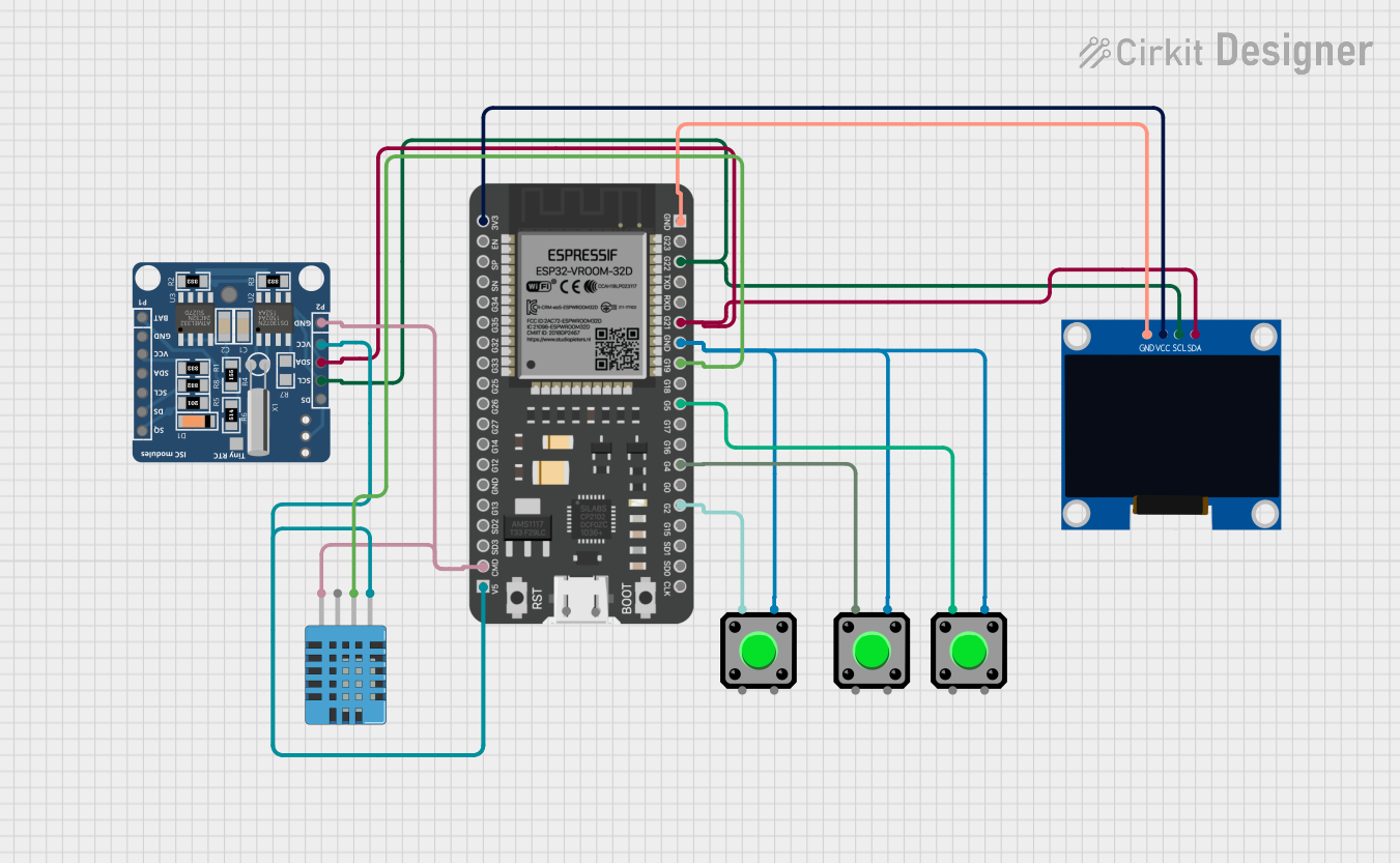
Circuit Documentation
Summary
This circuit is designed to interface an ESP32 microcontroller with a DHT11 humidity and temperature sensor, a DS1307 real-time clock (RTC), multiple pushbuttons, and a 128x64 OLED display. The ESP32 reads temperature and humidity data from the DHT11 sensor, displays the time and sensor data on the OLED display, and allows setting alarms using the pushbuttons. The circuit is also capable of connecting to a WiFi network and can synchronize the RTC with an NTP server.
Component List
ESP32 - 38 pins
- Description: A microcontroller with WiFi and Bluetooth capabilities.
- Pins: 3V3, EN, SP, SN, G34, G35, G32, G33, G25, G26, G27, G14, G12, GND, G13, SD2, SD3, CMD, 5V, G23, G22, TXD, RXD, G21, G19, G18, G5, G17, G16, G4, G0, G2, G15, SD1, SD0, CLK
DHT11 Humidity and Temperature Sensor
- Description: A sensor for measuring ambient temperature and humidity.
- Pins: VDD, DATA, NULL, GND
RTC DS1307
- Description: A real-time clock module for keeping track of the current time.
- Pins: DS, SCL, SDA, VCC, GND, BAT, SQ
Pushbutton (3 instances)
- Description: A simple pushbutton for user input.
- Pins: Pin 2, Pin 1, Pin 3, Pin 4
128x64 OLED Display (I2C IIC SPI Serial)
- Description: A small screen for displaying text and graphics.
- Pins: GND, SDA, SCL, VCC
Wiring Details
ESP32 - 38 pins
- 3V3 to OLED Display VCC
- GND to OLED Display GND, DHT11 GND, and RTC DS1307 GND
- 5V to RTC DS1307 VCC and DHT11 VDD
- G22 to RTC DS1307 SCL and OLED Display SCL
- G21 to RTC DS1307 SDA and OLED Display SDA
- G19 to DHT11 DATA
- G5 to Pushbutton (instance 1) Pin 1
- G4 to Pushbutton (instance 2) Pin 1
- G2 to Pushbutton (instance 3) Pin 1
DHT11 Humidity and Temperature Sensor
- VDD to ESP32 5V
- DATA to ESP32 G19
- GND to ESP32 GND
RTC DS1307
- VCC to ESP32 5V
- GND to ESP32 GND
- SCL to ESP32 G22
- SDA to ESP32 G21
Pushbuttons
- Pin 1 of each pushbutton to ESP32 G5, G4, and G2 respectively
- Pin 4 of all pushbuttons to ESP32 GND
128x64 OLED Display (I2C IIC SPI Serial)
- VCC to ESP32 3V3
- GND to ESP32 GND
- SCL to ESP32 G22
- SDA to ESP32 G21
Documented Code
The code provided is for the ESP32 microcontroller and includes the following functionalities:
- Initialization of the I2C interface for communication with the OLED display and RTC.
- Setup of the DHT11 sensor for reading temperature and humidity.
- Configuration of WiFi settings and web server for setting alarms through a web interface.
- Synchronization of the RTC with an NTP server.
- Handling of pushbuttons for setting alarms.
- Displaying time, temperature, humidity, and alarm status on the OLED display.
- Triggering alarms at set times with a buzzer.
#include <Wire.h>
#include <Adafruit_GFX.h>
#include <Adafruit_SSD1306.h>
#include <DHT.h>
#include <WiFi.h>
#include <WebServer.h>
#include <RTClib.h>
#include <WiFiUdp.h>
#include <NTPClient.h>

// ... (Code omitted for brevity)

void setup() {
  // Setup code including initialization of peripherals and WiFi connection
  // ...
}

void loop() {
  // Main loop handling web server, NTP updates, and display updates
  // ...
}

// Additional functions for handling web server requests, displaying information, and setting alarms
// ...
Note: The actual code is extensive and includes detailed functions for handling various tasks such as web server requests, displaying data on the OLED, reading sensor values, and managing alarms. The provided snippet is a high-level overview of the setup and loop functions, which are the core of the embedded application. For a complete understanding, one should refer to the full code provided in the input.