
555 Timer IC-Based LED Blinker with 4G Antenna and Battery Power
View and Edit Project In Cirkit Designer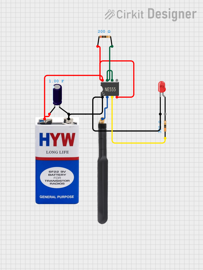
Circuit Documentation
Summary
This document provides a detailed overview of a circuit that includes a 555 Timer IC, a 9V battery, an electrolytic capacitor, a 4G antenna, a red LED, and two resistors. The circuit is designed to utilize the 555 Timer IC in an astable mode to generate a pulse, which is then used to drive the LED and interact with the 4G antenna.
Component List
555 Timer IC
- Pins: VCC+, Dis, Th, CV, Rst, Out, Trig, GND
- Description: A versatile timer IC used for generating precise time delays or oscillation.
- Purpose in Circuit: Used in astable mode to generate a continuous pulse.
9V Battery
- Pins: +, -
- Description: A standard 9V battery.
- Purpose in Circuit: Provides power to the circuit.
Electrolytic Capacitor
- Pins: -, +
- Description: A capacitor with a capacitance of 1 Farad.
- Purpose in Circuit: Used for timing and filtering purposes.
4G Antenna
- Pins: Connection
- Description: A 4G antenna for wireless communication.
- Purpose in Circuit: Interacts with the 555 Timer IC to transmit signals.
LED: Two Pin (red)
- Pins: cathode, anode
- Description: A red LED.
- Purpose in Circuit: Indicates the output pulse from the 555 Timer IC.
Resistor (330 Ohms)
- Pins: pin1, pin2
- Description: A resistor with a resistance of 330 Ohms.
- Purpose in Circuit: Limits current to the LED.
Resistor (200 Ohms)
- Pins: pin1, pin2
- Description: A resistor with a resistance of 200 Ohms.
- Purpose in Circuit: Sets the timing interval for the 555 Timer IC.
Wiring Details
555 Timer IC
- VCC+: Connected to the positive terminal of the 9V battery, the negative terminal of the electrolytic capacitor, and the reset pin of the 555 Timer IC.
- Dis: Connected to pin2 of the 200 Ohm resistor.
- Th: Connected to pin2 of the 200 Ohm resistor.
- CV: Not connected.
- Rst: Connected to the positive terminal of the 9V battery, the negative terminal of the electrolytic capacitor, and the VCC+ pin of the 555 Timer IC.
- Out: Connected to pin1 of the 330 Ohm resistor.
- Trig: Connected to the connection pin of the 4G antenna.
- GND: Connected to the positive terminal of the electrolytic capacitor, the cathode of the red LED, and the negative terminal of the 9V battery.
9V Battery
- +: Connected to the VCC+ pin of the 555 Timer IC, the reset pin of the 555 Timer IC, and the negative terminal of the electrolytic capacitor.
- -: Connected to the GND pin of the 555 Timer IC, the positive terminal of the electrolytic capacitor, and the cathode of the red LED.
Electrolytic Capacitor
- -: Connected to pin1 of the 200 Ohm resistor, the VCC+ pin of the 555 Timer IC, and the reset pin of the 555 Timer IC.
- +: Connected to the GND pin of the 555 Timer IC, the cathode of the red LED, and the negative terminal of the 9V battery.
4G Antenna
- Connection: Connected to the trigger pin of the 555 Timer IC.
LED: Two Pin (red)
- cathode: Connected to the GND pin of the 555 Timer IC, the positive terminal of the electrolytic capacitor, and the negative terminal of the 9V battery.
- anode: Not connected.
Resistor (330 Ohms)
- pin1: Connected to the output pin of the 555 Timer IC.
- pin2: Not connected.
Resistor (200 Ohms)
- pin1: Connected to the negative terminal of the electrolytic capacitor, the VCC+ pin of the 555 Timer IC, and the reset pin of the 555 Timer IC.
- pin2: Connected to the discharge pin and threshold pin of the 555 Timer IC.
Code
No microcontroller code is provided for this circuit.