
Cirkit Designer
Your all-in-one circuit design IDE
Home /
Project Documentation
ESP32 and W5500 Ethernet Module Controlled 8-Channel Relay
Circuit Documentation
Summary
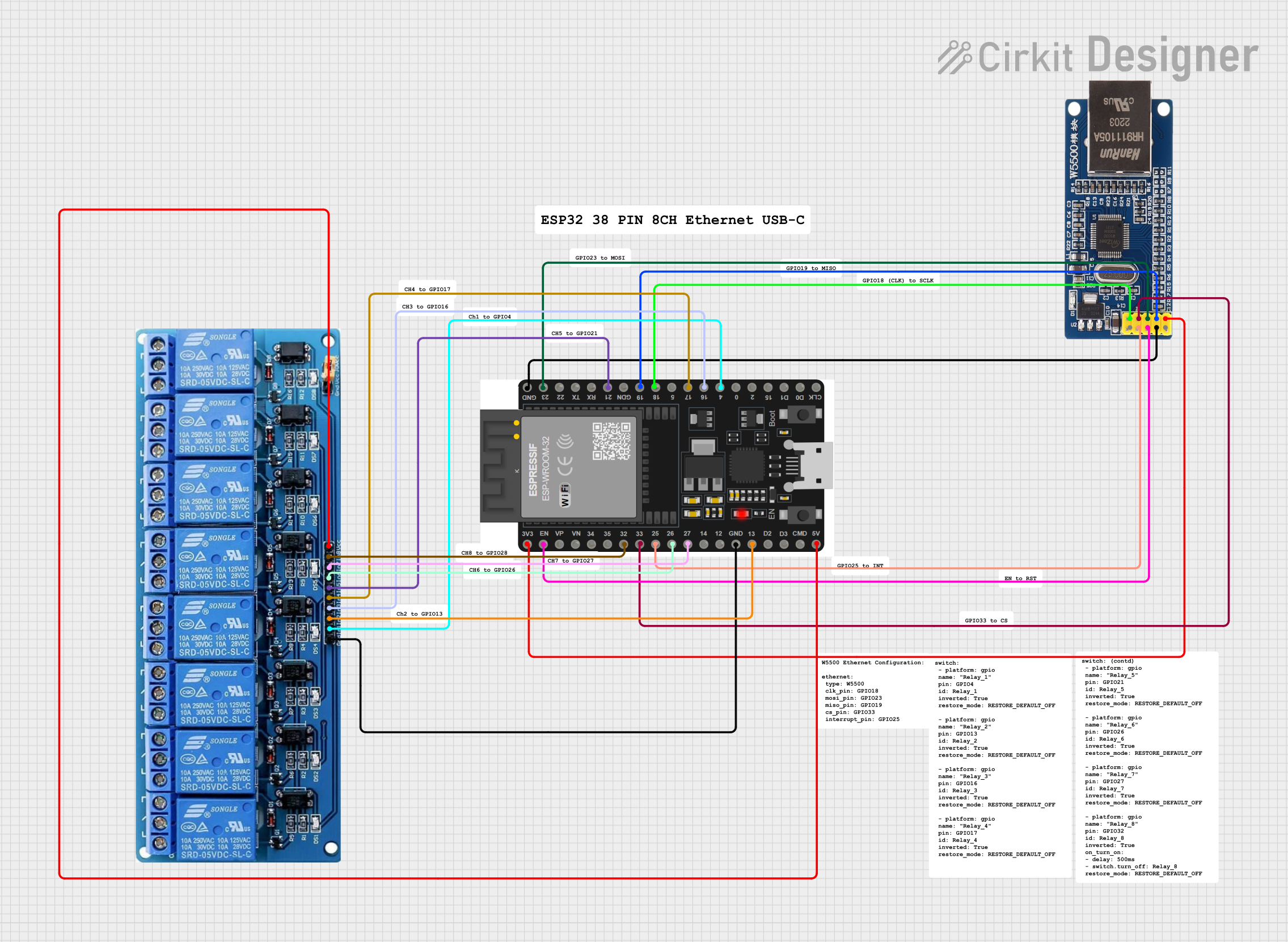
This circuit integrates an Ethernet module (W5500) with an ESP32 microcontroller to enable network connectivity. Additionally, it controls an 8-channel 5V relay module, allowing the ESP32 to switch external devices on and off. The Ethernet module is interfaced with the ESP32 via SPI communication, and the relay module is controlled through GPIO pins.
Component List
Module Ethernet W5500
- Description: An Ethernet module based on the W5500 chip, which provides TCP/IP capabilities.
- Pins: NC, INT, RST, GND, 5V, SCK, SS, MOSI, MISO, 3.3V
ESP32 38 PINS
- Description: A microcontroller with Wi-Fi and Bluetooth capabilities, featuring a wide range of GPIO pins.
- Pins: GND, 23, 22/SCL, 1, 2, 21/SDA, 19, 18, 5, 17/TX2, 16/RX2, 4, 0, 15, D1, D0, CLK, 3V3, EN, VP, VN, 34, 35, 32, 33, 25, 26, 27, 14, 12, 13, D2, D3, 11, 5V/VIN
5V 8Channel Relay
- Description: A relay module with 8 channels that can be individually controlled, suitable for switching high-power devices.
- Pins: GND, IN1, IN2, IN3, IN4, IN5, IN6, IN7, IN8, VCC, NC, C, NO
Wiring Details
Module Ethernet W5500
- INT connected to ESP32 pin 25
- RST connected to ESP32 pin EN
- GND connected to ESP32 GND
- SCK connected to ESP32 pin 18
- SS connected to ESP32 pin 33
- MOSI connected to ESP32 pin 23
- MISO connected to ESP32 pin 19
- 3.3V connected to ESP32 pin 3V3
ESP32 38 PINS
- GND connected to Ethernet Module GND and Relay Module GND
- Pins 23, 18, 33, 19, 25, EN, 3V3 connected to Ethernet Module as per SPI and control signals
- Pins 21/SDA, 17/TX2, 16/RX2, 4, 32, 26, 27, 13, 5V/VIN connected to Relay Module for control signals and power
5V 8Channel Relay
- IN5 connected to ESP32 pin 21/SDA
- IN4 connected to ESP32 pin 17/TX2
- IN3 connected to ESP32 pin 16/RX2
- IN1 connected to ESP32 pin 4
- IN8 connected to ESP32 pin 32
- IN6 connected to ESP32 pin 26
- IN7 connected to ESP32 pin 27
- IN2 connected to ESP32 pin 13
- GND connected to ESP32 GND
- VCC connected to ESP32 pin 5V/VIN
Documented Code
Microcontroller: ESP32 (W5500 Ethernet Module)
void setup() {
  // put your setup code here, to run once:

}

void loop() {
  // put your main code here, to run repeatedly:

}
Note: The provided code is a template and does not include specific functionality. It should be populated with the initialization of the Ethernet module and the control logic for the relay module.