
Arduino-Based Wireless Motor and Water Pump Controller with nRF24L01 and Joystick
View and Edit Project In Cirkit Designer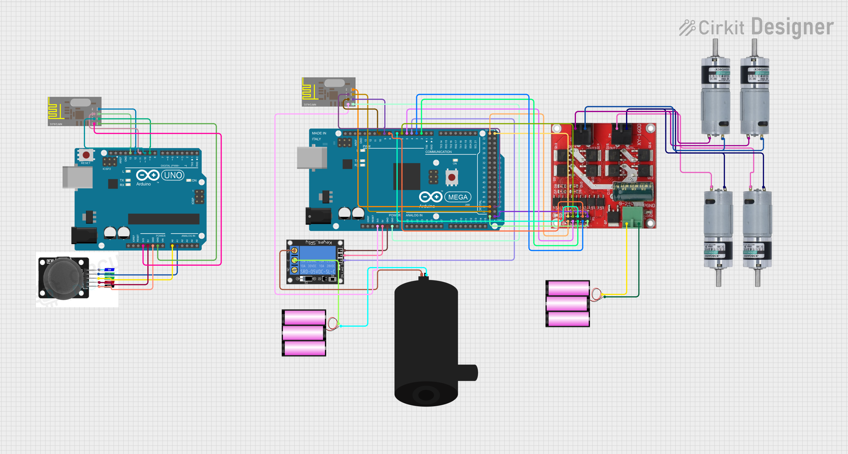
Circuit Documentation
Summary
This circuit involves an Arduino UNO and an Arduino Mega 2560, each interfacing with various components to control motors, a water pump, and communicate wirelessly using nRF24L01 modules. The Arduino UNO reads joystick inputs and sends data wirelessly to the Arduino Mega 2560, which controls the motors and a water pump via a relay.
Component List
nRF24L01
- Description: Wireless transceiver module
- Pins: GND, VCC, CE, CSN, SCK, MOSI, MISO, IRQ
L298 Dual H Bridge Motor Speed Controller
- Description: Motor driver for controlling two motors
- Pins: 5V, ENA, IN1, IN2, GND, IN4, IN3, 12V, Motor 1 Power, Motor 1 GND, Motor 2 Power, Motor 2 GND
Joystick Module
- Description: Joystick for user input
- Pins: SW, VRY, VRX, VCC, GND
1-Channel Relay (5V 10A)
- Description: Relay module for switching high-power devices
- Pins: NC, signal, C, power, NO, ground
Water Pump
- Description: Pump for moving water
- Pins: positive, negative
Arduino UNO
- Description: Microcontroller board
- Pins: UNUSED, IOREF, Reset, 3.3V, 5V, GND, Vin, A0, A1, A2, A3, A4, A5, SCL, SDA, AREF, D13, D12, D11, D10, D9, D8, D7, D6, D5, D4, D3, D2, D1, D0
Arduino Mega 2560
- Description: Microcontroller board with more I/O pins
- Pins: IOREF, RESET, 3V3, 5V, GND, VIN, A0, A1, A2, A3, A4, A5, A6, A7, A8, A9, A10, A11, A12, A13, A14, A15, D21/SCL, D20/SDA, D19/RX1, D18/TX1, D17 PWM/RX2, D16 PWM/TX2, D15/RX3, D14/TX3, D0 RX0, D1 TX0, D2 PWM, D3 PWM, D4 PWM, D5 PWM, D6 PWM, D7 PWM, D8 PWM, D9 PWM, D10 PWM, D11 PWM, D12 PWM, D13 PWM, AREF, SDA, SCL, D52, D50, D48, D46, D44, D42, D40, D38, D36, D34, D32, D30, D28, D26, D24, D22, D53, D51, D49, D47, D45, D43, D41, D39, D37, D35, D33, D31, D29, D27, D25, D23, 6swdw
Battery 12V
- Description: Power source
- Pins: +, -
MRB Planetary Gearbox Motor
- Description: Motor with planetary gearbox
- Pins: +, -
Wiring Details
nRF24L01 (Connected to Arduino UNO)
- GND: Connected to Arduino UNO GND
- VCC: Connected to Arduino UNO 3.3V
- CE: Connected to Arduino UNO D9
- CSN: Connected to Arduino UNO D10
- SCK: Connected to Arduino UNO D13
- MOSI: Connected to Arduino UNO D11
- MISO: Connected to Arduino UNO D12
L298 Dual H Bridge Motor Speed Controller (Connected to Arduino Mega 2560)
- 5V: Connected to Arduino Mega 2560 5V
- ENA: Connected to Arduino Mega 2560 D5 PWM
- IN1: Connected to Arduino Mega 2560 D2 PWM
- IN2: Connected to Arduino Mega 2560 D3 PWM
- GND: Connected to Arduino Mega 2560 GND
- IN4: Connected to Arduino Mega 2560 D8 PWM
- IN3: Connected to Arduino Mega 2560 D7 PWM
- ENA: Connected to Arduino Mega 2560 D6 PWM
- 12V: Connected to Battery 12V +
- Motor 1 Power: Connected to MRB Planetary Gearbox Motor +
- Motor 1 GND: Connected to MRB Planetary Gearbox Motor -
- Motor 2 Power: Connected to MRB Planetary Gearbox Motor -
- Motor 2 GND: Connected to MRB Planetary Gearbox Motor +
Joystick Module (Connected to Arduino UNO)
- VRY: Connected to Arduino UNO A1
- VRX: Connected to Arduino UNO A0
- VCC: Connected to Arduino UNO 5V
- GND: Connected to Arduino UNO GND
1-Channel Relay (Connected to Arduino Mega 2560)
- power: Connected to Arduino Mega 2560 5V
- ground: Connected to Arduino Mega 2560 GND
- signal: Connected to Arduino Mega 2560 D4 PWM
- C: Connected to Battery 12V +
- NO: Connected to Water Pump positive
Water Pump
- positive: Connected to 1-Channel Relay NO
- negative: Connected to Battery 12V -
nRF24L01 (Connected to Arduino Mega 2560)
- GND: Connected to Arduino Mega 2560 GND
- VCC: Connected to Arduino Mega 2560 3V3
- CE: Connected to Arduino Mega 2560 D9 PWM
- CSN: Connected to Arduino Mega 2560 D10 PWM
- SCK: Connected to Arduino Mega 2560 D52
- MISO: Connected to Arduino Mega 2560 D50
- MOSI: Connected to Arduino Mega 2560 D51
Code Documentation
Arduino UNO Code
#include <SPI.h>
#include <nRF24L01.h>
#include <RF24.h>

// Pin untuk Joystick
const int joystickXPin = A0; // X-axis
const int joystickYPin = A1; // Y-axis

// Pin untuk Button Relay
const int buttonPin = 2; // Sambungkan push button ke Pin 2

// Konfigurasi nRF24L01
RF24 radio(9, 10); // CE, CSN
const byte address[6] = "00001";

void setup() {
  // Tetapkan pin untuk button
  pinMode(buttonPin, INPUT_PULLUP); // Button dengan pull-up resistor

  // Mulakan Serial dan nRF24L01
  Serial.begin(9600);
  radio.begin();
  radio.openWritingPipe(address);
  radio.setPALevel(RF24_PA_HIGH); // Tetapkan kuasa tinggi untuk kestabilan
  radio.stopListening();
}

void loop() {
  // Baca nilai joystick
  int joyX = analogRead(joystickXPin);
  int joyY = analogRead(joystickYPin);

  // Baca status button
  bool buttonState = digitalRead(buttonPin) == LOW; // LOW jika button ditekan

  // Data yang akan dihantar
  int data[3] = {joyX, joyY, buttonState}; // Tambah status button sebagai elemen ketiga

  // Hantar data ke penerima
  bool success = radio.write(&data, sizeof(data));

  // Paparkan status penghantaran di Serial Monitor
  if (success) {
    Serial.print("Data dihantar: ");
    Serial.print("X: ");
    Serial.print(joyX);
    Serial.print(" Y: ");
    Serial.print(joyY);
    Serial.print(" Relay: ");
    Serial.println(buttonState ? "ON" : "OFF");
  } else {
    Serial.println("Penghantaran data gagal");
  }

  delay(100); // Kurangkan frekuensi penghantaran untuk kestabilan
}
Arduino Mega 2560 Code
void setup() {
  // put your setup code here, to run once:
}

void loop() {
  // put your main code here, to run repeatedly:
}
This documentation provides a comprehensive overview of the circuit, including a summary, detailed component list, wiring details, and the code used for the microcontrollers.