
ESP32-Based Smart RGB LED and Servo Control with RFID and OLED Display
View and Edit Project In Cirkit Designer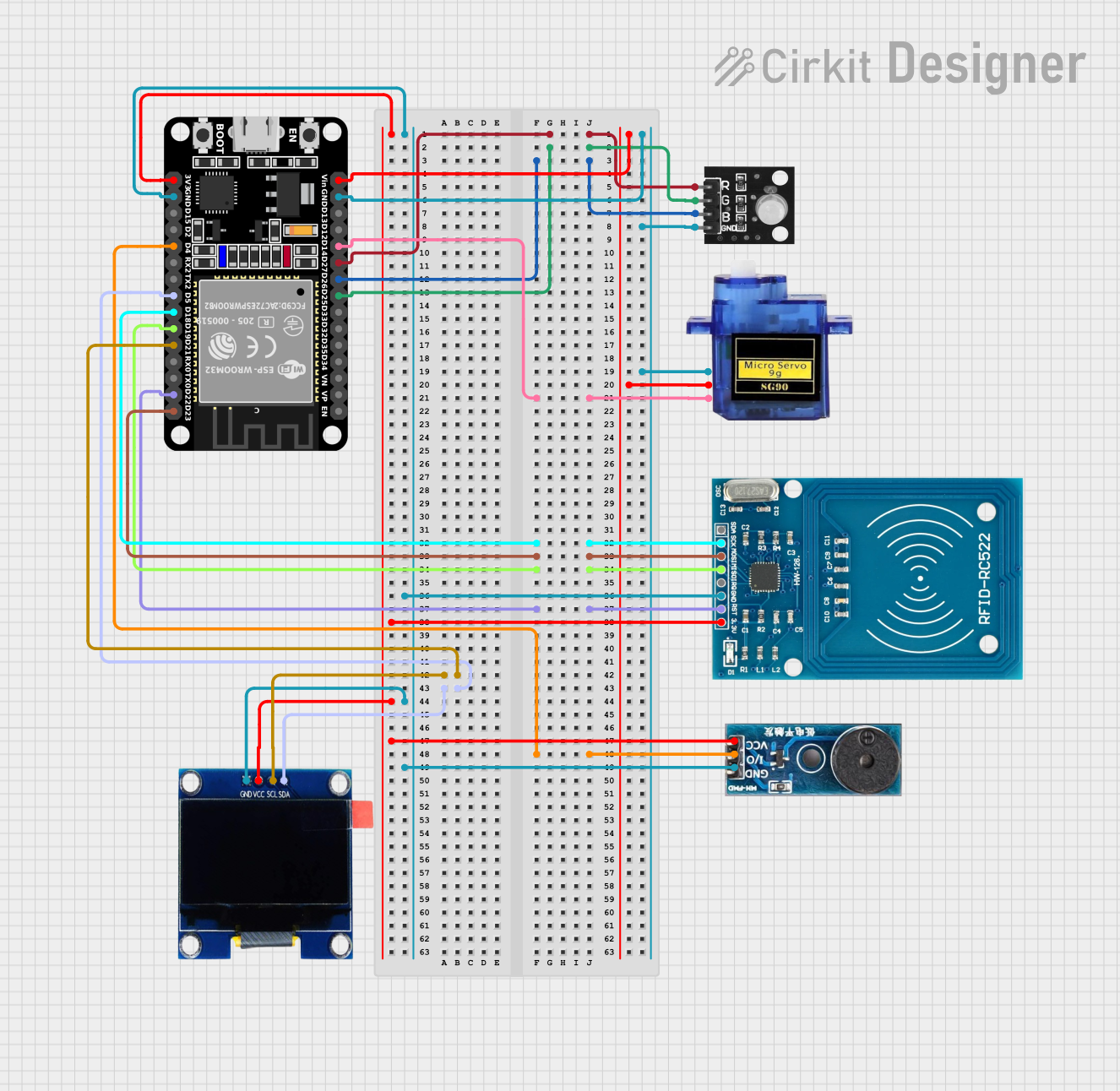
Circuit Documentation
Summary
This document provides a detailed overview of a circuit that includes an ESP32 microcontroller, an RGB LED module, a micro servo, an RFID-RC522 module, an OLED display, and a buzzer module. The ESP32 microcontroller is the central unit that controls the other components. The circuit is designed to demonstrate basic control of an RGB LED, a servo motor, an RFID reader, an OLED display, and a buzzer.
Component List
ESP32 (30 pin)
- Description: A powerful microcontroller with built-in Wi-Fi and Bluetooth capabilities.
- Pins: EN, VP, VN, D34, D35, D32, D33, D25, D26, D27, D14, D12, D13, GND, Vin, D23, D22, TX0, RX0, D21, D19, D18, D5, TX2, RX2, D4, D2, D15, 3V3
RGB LED Module
- Description: A module containing red, green, and blue LEDs that can be controlled individually.
- Pins: +VCC Red, +VCC Green, +VCC Blue, GND
Micro Servo 9G
- Description: A small servo motor used for precise control of angular position.
- Pins: GND, +5V, PWM
RFID-RC522
- Description: An RFID reader module used for reading RFID tags.
- Pins: VCC (3.3V), RST, GND, IRQ, MISO, MOSI, SCK, SDA
OLED 1.3"
- Description: A small OLED display used for displaying text and graphics.
- Pins: GND, VCC, SCL, SDA
Buzzer Module
- Description: A module that produces sound when a voltage is applied.
- Pins: GND, Vcc, I/O
Wiring Details
ESP32 (30 pin)
- D27 is connected to +VCC Red of the RGB LED module.
- D25 is connected to +VCC Green of the RGB LED module.
- D26 is connected to +VCC Blue of the RGB LED module.
- D14 is connected to PWM of the Micro Servo 9G.
- D18 is connected to SCK of the RFID-RC522.
- D23 is connected to MOSI of the RFID-RC522.
- D19 is connected to MISO of the RFID-RC522.
- D22 is connected to RST of the RFID-RC522.
- D21 is connected to SCL of the OLED 1.3".
- D5 is connected to SDA of the OLED 1.3".
- D4 is connected to I/O of the Buzzer Module.
- 3V3 is connected to VCC (3.3V) of the RFID-RC522, VCC of the OLED 1.3", and Vcc of the Buzzer Module.
- GND is connected to GND of the RFID-RC522, GND of the OLED 1.3", GND of the Buzzer Module, GND of the RGB LED module, and GND of the Micro Servo 9G.
- Vin is connected to +5V of the Micro Servo 9G.
RGB LED Module
- +VCC Red is connected to D27 of the ESP32.
- +VCC Green is connected to D25 of the ESP32.
- +VCC Blue is connected to D26 of the ESP32.
- GND is connected to GND of the ESP32.
Micro Servo 9G
- GND is connected to GND of the ESP32.
- +5V is connected to Vin of the ESP32.
- PWM is connected to D14 of the ESP32.
RFID-RC522
- VCC (3.3V) is connected to 3V3 of the ESP32.
- RST is connected to D22 of the ESP32.
- GND is connected to GND of the ESP32.
- SCK is connected to D18 of the ESP32.
- MISO is connected to D19 of the ESP32.
- MOSI is connected to D23 of the ESP32.
- SDA is not connected in this circuit.
OLED 1.3"
- GND is connected to GND of the ESP32.
- VCC is connected to 3V3 of the ESP32.
- SCL is connected to D21 of the ESP32.
- SDA is connected to D5 of the ESP32.
Buzzer Module
- GND is connected to GND of the ESP32.
- Vcc is connected to 3V3 of the ESP32.
- I/O is connected to D4 of the ESP32.
Code Documentation
ESP32 Code
#define RED_PIN 25
#define GREEN_PIN 26
#define BLUE_PIN 27

void setup() {
  pinMode(RED_PIN, OUTPUT);
  pinMode(GREEN_PIN, OUTPUT);
  pinMode(BLUE_PIN, OUTPUT);
}

void loop() {
  // Turn on Red
  digitalWrite(RED_PIN, HIGH);
  digitalWrite(GREEN_PIN, LOW);
  digitalWrite(BLUE_PIN, LOW);
  delay(1000);

  // Turn on Green
  digitalWrite(RED_PIN, LOW);
  digitalWrite(GREEN_PIN, HIGH);
  digitalWrite(BLUE_PIN, LOW);
  delay(1000);

  // Turn on Blue
  digitalWrite(RED_PIN, LOW);
  digitalWrite(GREEN_PIN, LOW);
  digitalWrite(BLUE_PIN, HIGH);
  delay(1000);
}
This code sets up the ESP32 to control the RGB LED module. It defines the pins connected to the red, green, and blue LEDs and sets them as output pins. The loop function cycles through turning on each color for one second.