Arduino UNO Controlled Bluetooth Servo Motor

Circuit Documentation
Summary of the Circuit
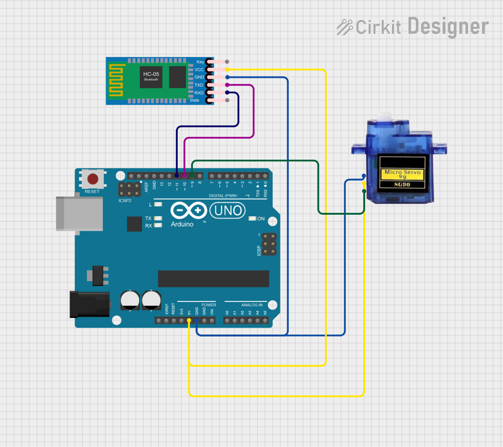
This circuit integrates an Arduino UNO microcontroller with an HC-05 Bluetooth Module and a Micro servo 9G. The Arduino UNO serves as the central processing unit, controlling the servo motor and communicating with external devices via the Bluetooth module. The servo is powered and controlled by the Arduino, and the Bluetooth module enables wireless communication, potentially for remote control or telemetry purposes.
Component List
Arduino UNO
- Description: A microcontroller board based on the ATmega328P.
- Pins: UNUSED, IOREF, Reset, 3.3V, 5V, GND, Vin, A0-A5, SCL, SDA, AREF, D0-D13.
- Purpose: Acts as the central controller for the circuit, interfacing with the Bluetooth module and controlling the servo motor.
HC-05 Bluetooth Module
- Description: A wireless communication module that allows for Bluetooth connectivity.
- Pins: Key, VCC, TXD, RXD, State, GND.
- Purpose: Provides a means for wireless communication between the Arduino and other Bluetooth-enabled devices.
Micro servo 9G
- Description: A small and lightweight servo motor suitable for small-scale projects.
- Pins: GND, +5V, PWM.
- Purpose: Receives control signals from the Arduino to adjust its position accordingly.
Wiring Details
Arduino UNO
- 5V: Provides power to the HC-05 Bluetooth Module and Micro servo 9G.
- GND: Common ground with HC-05 Bluetooth Module and Micro servo 9G.
- D11: Connected to RXD on the HC-05 Bluetooth Module for serial communication.
- D10: Connected to TXD on the HC-05 Bluetooth Module for serial communication.
- D9: Connected to the PWM input of the Micro servo 9G to control the servo position.
HC-05 Bluetooth Module
- VCC: Powered by the 5V output from the Arduino UNO.
- GND: Common ground with Arduino UNO.
- TXD: Sends data to the Arduino UNO via pin D10.
- RXD: Receives data from the Arduino UNO via pin D11.
Micro servo 9G
- +5V: Powered by the 5V output from the Arduino UNO.
- GND: Common ground with Arduino UNO.
- PWM: Receives pulse-width modulation signals from pin D9 of the Arduino UNO to control the servo's position.
Documented Code
Arduino UNO Code (sketch.ino)
void setup() {
  // put your setup code here, to run once:

}

void loop() {
  // put your main code here, to run repeatedly:

}
This code template provides the basic structure for an Arduino sketch, with setup() and loop() functions defined. The setup() function is intended for initialization code that runs once when the microcontroller is powered on or reset. The loop() function contains the main logic of the program, which is executed repeatedly as long as the Arduino is powered.
Note: The actual implementation details for controlling the servo and managing Bluetooth communication should be added to the setup() and loop() functions as needed for the specific application.
This documentation provides an overview of the circuit components, their wiring, and the initial code structure for the Arduino UNO. Further details and specific functionalities should be added to the code to fulfill the desired operation of the circuit.