
Arduino Mega 2560 Controlled Dual DC Motor System with Rotary and Optical Encoders
View and Edit Project In Cirkit Designer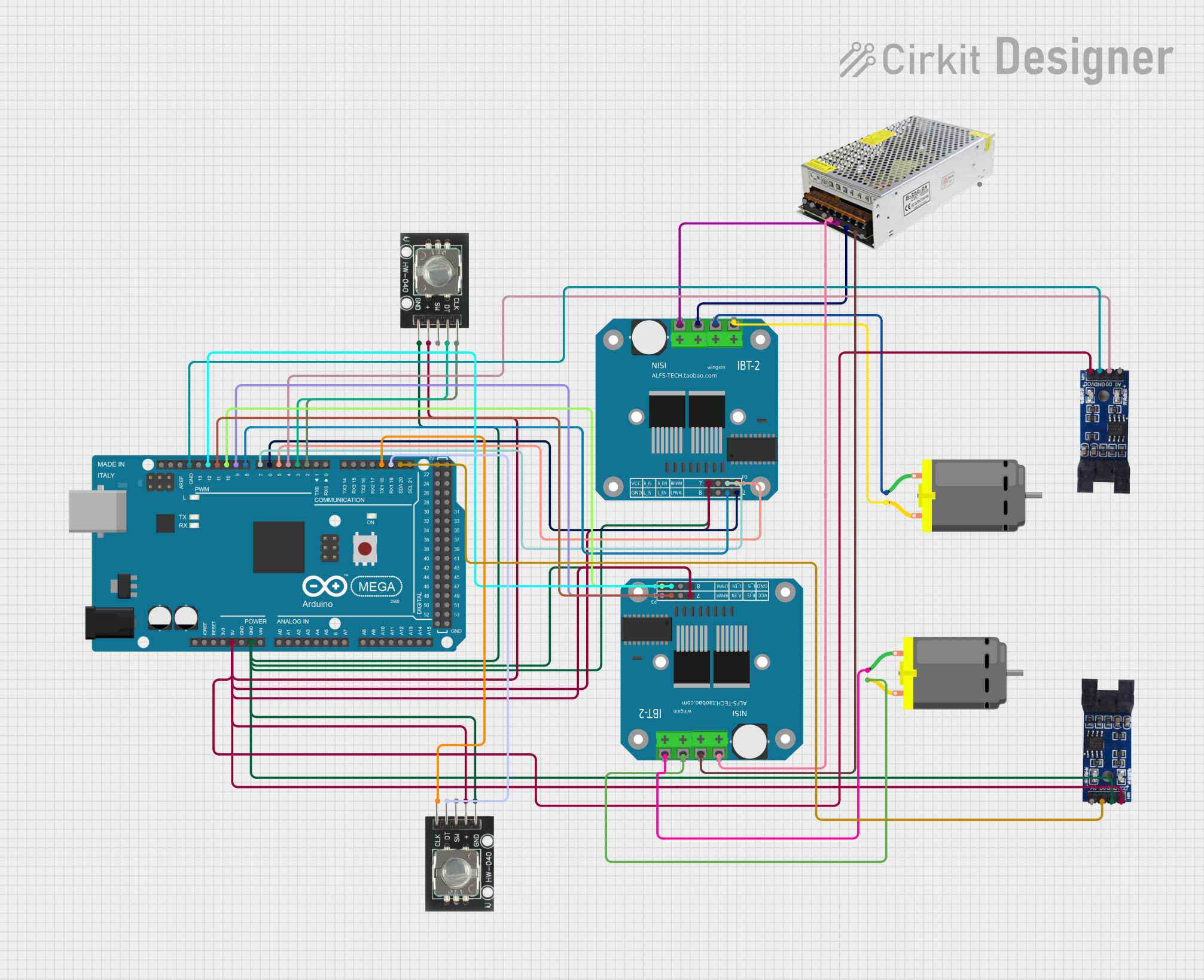
Circuit Documentation
Summary
This circuit involves an Arduino Mega 2560 microcontroller, two BTS7960 motor drivers, two DC motors, two HW-040 rotary encoders, two optical encoder sensor modules, and a power supply unit. The circuit is designed to control the DC motors using the motor drivers, with feedback from the rotary and optical encoders. The Arduino Mega 2560 serves as the central controller, interfacing with all other components.
Component List
Arduino Mega 2560
- Description: A microcontroller board based on the ATmega2560.
- Pins: IOREF, RESET, 3V3, 5V, GND, VIN, A0-A15, D21/SCL, D20/SDA, D19/RX1, D18/TX1, D17 PWM/RX2, D16 PWM/TX2, D15/RX3, D14/TX3, D0 RX0, D1 TX0, D2-D13 PWM, AREF, SDA, SCL, D52, D50, D48, D46, D44, D42, D40, D38, D36, D34, D32, D30, D28, D26, D24, D22, D53, D51, D49, D47, D45, D43, D41, D39, D37, D35, D33, D31, D29, D27, D25, D23.
BTS7960 Motor Driver
- Description: A high-current motor driver module.
- Pins: Pin 1, Pin 2, Pin 3, Pin 4, Pin 5, Pin 6, Pin 7, Pin 8, Pin 9, Pin 10, Pin 11, Pin 12.
DC Motor
- Description: A standard DC motor.
- Pins: pin 1, pin 2.
HW-040 Rotary Encoder
- Description: A rotary encoder module.
- Pins: GND, +, SW, DT, CLK.
Optical Encoder Sensor Module
- Description: An optical encoder sensor module.
- Pins: A0, D0, GND, VCC.
Power Supply Unit (POWERSUP)
- Description: A power supply unit.
- Pins: L, N, COM, V+.
Wiring Details
Arduino Mega 2560
- 5V is connected to:
- HW-040 Rotary Encoder (+)
- Optical Encoder Sensor Module (VCC)
- BTS7960 Motor Driver (Pin 5)
- GND is connected to:
- HW-040 Rotary Encoder (GND)
- Optical Encoder Sensor Module (GND)
- BTS7960 Motor Driver (Pin 1)
- D20/SDA is connected to:
- Optical Encoder Sensor Module (D0)
- D19/RX1 is connected to:
- HW-040 Rotary Encoder (DT)
- D18/TX1 is connected to:
- HW-040 Rotary Encoder (CLK)
- D2 PWM is connected to:
- HW-040 Rotary Encoder (CLK)
- D3 PWM is connected to:
- HW-040 Rotary Encoder (DT)
- D4 PWM is connected to:
- Optical Encoder Sensor Module (D0)
- D5 PWM is connected to:
- BTS7960 Motor Driver (Pin 8)
- D6 PWM is connected to:
- BTS7960 Motor Driver (Pin 4)
- D7 PWM is connected to:
- BTS7960 Motor Driver (Pin 7)
- D8 PWM is connected to:
- BTS7960 Motor Driver (Pin 3)
- D9 PWM is connected to:
- BTS7960 Motor Driver (Pin 8)
- D10 PWM is connected to:
- BTS7960 Motor Driver (Pin 4)
- D11 PWM is connected to:
- BTS7960 Motor Driver (Pin 7)
- D12 PWM is connected to:
- BTS7960 Motor Driver (Pin 3)
BTS7960 Motor Driver
- Pin 5 is connected to:
- Arduino Mega 2560 (5V)
- Pin 1 is connected to:
- Arduino Mega 2560 (GND)
- Pin 8 is connected to:
- Arduino Mega 2560 (D5 PWM)
- Arduino Mega 2560 (D9 PWM)
- Pin 4 is connected to:
- Arduino Mega 2560 (D6 PWM)
- Arduino Mega 2560 (D10 PWM)
- Pin 7 is connected to:
- Arduino Mega 2560 (D7 PWM)
- Arduino Mega 2560 (D11 PWM)
- Pin 3 is connected to:
- Arduino Mega 2560 (D8 PWM)
- Arduino Mega 2560 (D12 PWM)
- Pin 9 is connected to:
- DC Motor (pin 2)
- Pin 10 is connected to:
- DC Motor (pin 1)
- Pin 11 is connected to:
- Power Supply Unit (V+)
- Pin 12 is connected to:
- Power Supply Unit (COM)
DC Motor
- pin 2 is connected to:
- BTS7960 Motor Driver (Pin 9)
- pin 1 is connected to:
- BTS7960 Motor Driver (Pin 10)
HW-040 Rotary Encoder
- + is connected to:
- Arduino Mega 2560 (5V)
- GND is connected to:
- Arduino Mega 2560 (GND)
- DT is connected to:
- Arduino Mega 2560 (D19/RX1)
- Arduino Mega 2560 (D3 PWM)
- CLK is connected to:
- Arduino Mega 2560 (D18/TX1)
- Arduino Mega 2560 (D2 PWM)
Optical Encoder Sensor Module
- VCC is connected to:
- Arduino Mega 2560 (5V)
- GND is connected to:
- Arduino Mega 2560 (GND)
- D0 is connected to:
- Arduino Mega 2560 (D20/SDA)
- Arduino Mega 2560 (D4 PWM)
Power Supply Unit (POWERSUP)
- V+ is connected to:
- BTS7960 Motor Driver (Pin 11)
- COM is connected to:
- BTS7960 Motor Driver (Pin 12)
Documented Code
Arduino Mega 2560 Code
void setup() {
  // put your setup code here, to run once:

}

void loop() {
  // put your main code here, to run repeatedly:

}
This code is a basic template for the Arduino Mega 2560. The setup() function is where you initialize your components and settings, and the loop() function is where the main logic of your program runs repeatedly.