
Circuit Documentation
Summary
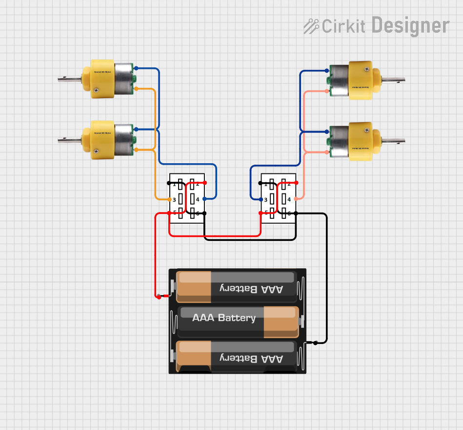
This circuit consists of two DPDT switches, four center shaft metal geared motors, and a 3xAA battery pack. The circuit is designed to control the motors using the DPDT switches, which can change the direction of the motors by reversing the polarity of the connections.
Component List
DPDT Switch
- Description: Double Pole Double Throw switch used to control the direction of current flow.
- Pins: 2, 4, 6, 5, 3, 1
Center Shaft Metal Geared Motor
- Description: A motor with a metal gear system for increased torque.
- Pins: +, -
3xAA Battery Pack
- Description: A battery holder for three AA batteries providing power to the circuit.
- Pins: VCC, GND
Wiring Details
DPDT Switch 1
- Pin 2: Connected to Pin 5 of the same switch and VCC of the 3xAA Battery Pack. Also connected to Pin 2 and Pin 5 of DPDT Switch 2.
- Pin 4: Connected to the positive terminals (+) of Motor 1 and Motor 2.
- Pin 6: Connected to Pin 1 of the same switch and GND of the 3xAA Battery Pack. Also connected to Pin 6 and Pin 1 of DPDT Switch 2.
- Pin 3: Connected to the negative terminals (-) of Motor 1 and Motor 2.
DPDT Switch 2
- Pin 2: Connected to Pin 5 of the same switch and VCC of the 3xAA Battery Pack. Also connected to Pin 2 and Pin 5 of DPDT Switch 1.
- Pin 4: Connected to the positive terminals (+) of Motor 3 and Motor 4.
- Pin 6: Connected to Pin 1 of the same switch and GND of the 3xAA Battery Pack. Also connected to Pin 6 and Pin 1 of DPDT Switch 1.
- Pin 3: Connected to the negative terminals (-) of Motor 3 and Motor 4.
Center Shaft Metal Geared Motor 1
- Pin +: Connected to Pin 4 of DPDT Switch 1.
- Pin -: Connected to Pin 3 of DPDT Switch 1.
Center Shaft Metal Geared Motor 2
- Pin +: Connected to Pin 4 of DPDT Switch 1.
- Pin -: Connected to Pin 3 of DPDT Switch 1.
Center Shaft Metal Geared Motor 3
- Pin +: Connected to Pin 4 of DPDT Switch 2.
- Pin -: Connected to Pin 3 of DPDT Switch 2.
Center Shaft Metal Geared Motor 4
- Pin +: Connected to Pin 4 of DPDT Switch 2.
- Pin -: Connected to Pin 3 of DPDT Switch 2.
3xAA Battery Pack
- Pin VCC: Connected to Pin 2 and Pin 5 of both DPDT Switch 1 and DPDT Switch 2.
- Pin GND: Connected to Pin 6 and Pin 1 of both DPDT Switch 1 and DPDT Switch 2.
Code
There is no microcontroller code associated with this circuit.