Arduino Nano-Based Wireless Joystick and Motion Controller
Circuit Documentation
Summary of the Circuit
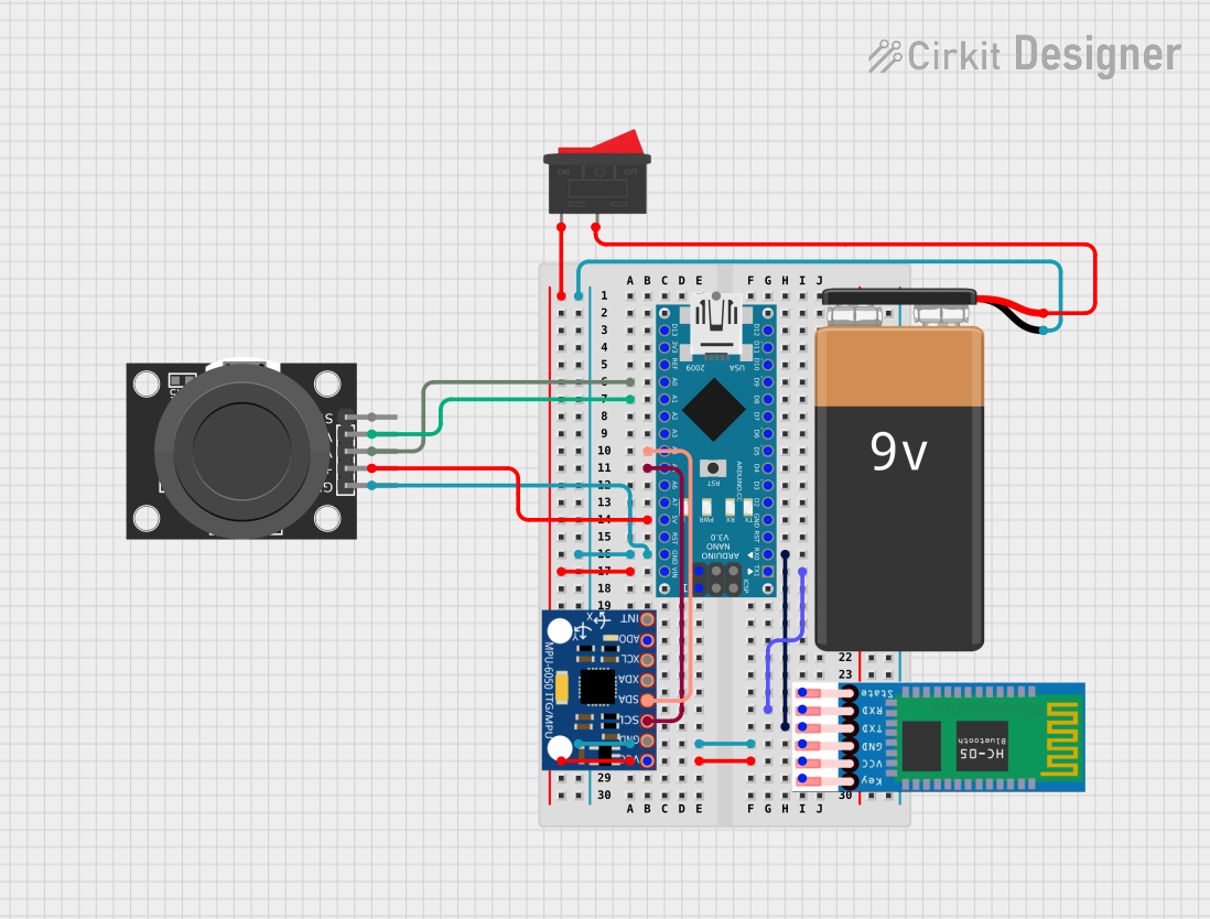
This circuit integrates an Arduino Nano microcontroller with several peripherals: an HC-05 Bluetooth module for wireless communication, an MPU-6050 accelerometer and gyroscope for motion sensing, a KY-023 Dual Axis Joystick Module for manual input, and a 9V battery with a rocker switch for power supply. The Arduino Nano serves as the central processing unit, interfacing with the sensors and the Bluetooth module to possibly collect data and control or communicate with other devices.
Component List
Arduino Nano
- Microcontroller board based on the ATmega328P
- It has a variety of digital and analog I/O pins
- Can be powered via USB or an external power source
HC-05 Bluetooth Module
- Bluetooth module for serial communication
- Typically used for wireless data transfer between two microcontrollers or a microcontroller and a smartphone
MPU-6050
- Motion sensor with a 3-axis gyroscope and a 3-axis accelerometer
- Utilizes I2C communication
KY-023 Dual Axis Joystick Module
- Manual input device with two analog axes
- Includes a pushbutton switch
9V Battery
- Standard 9V battery used as the power source
Rocker Switch
- A simple on-off switch to control the power supply to the circuit
Wiring Details
Arduino Nano
VINconnected to the Rocker Switch for power inputGNDconnected to the common ground of the circuitA0connected to theVRxpin of the KY-023 Joystick ModuleA1connected to theVRypin of the KY-023 Joystick ModuleA4(SDA) connected to theSDApin of the MPU-6050A5(SCL) connected to theSCLpin of the MPU-60505Voutput provides power to the KY-023 Joystick Module, HC-05, and MPU-6050D0/RXconnected to theTXDpin of the HC-05D1/TXconnected to theRXDpin of the HC-05
HC-05 Bluetooth Module
VCCconnected to5Von the Arduino NanoGNDconnected to the common ground of the circuitTXDconnected toD0/RXon the Arduino NanoRXDconnected toD1/TXon the Arduino Nano
MPU-6050
VCCconnected to5Von the Arduino NanoGNDconnected to the common ground of the circuitSCLconnected toA5on the Arduino NanoSDAconnected toA4on the Arduino Nano
KY-023 Dual Axis Joystick Module
+5Vconnected to5Von the Arduino NanoGNDconnected to the common ground of the circuitVRxconnected toA0on the Arduino NanoVRyconnected toA1on the Arduino Nano
9V Battery
+connected to pin2of the Rocker Switch-connected to the common ground of the circuit
Rocker Switch
- Pin
1connected toVINon the Arduino Nano - Pin
2connected to the+of the 9V Battery
Documented Code
Arduino Nano Code (sketch.ino)
void setup() {
  // put your setup code here, to run once:

}

void loop() {
  // put your main code here, to run repeatedly:

}
This is the basic structure of an Arduino sketch, with two primary functions: setup() and loop(). The setup() function is called once when the sketch starts and is used for initializing settings, pin modes, starting libraries, etc. The loop() function is called repeatedly and contains the main logic of the sketch. The provided code is a template and does not contain any specific functionality. Additional code would be required to initialize and use the connected modules and sensors.