Cirkit Designer
Your all-in-one circuit design IDE
Home /
Project Documentation
Arduino UNO Ultrasonic Distance Sensor with LED Indicators
Circuit Documentation
Summary
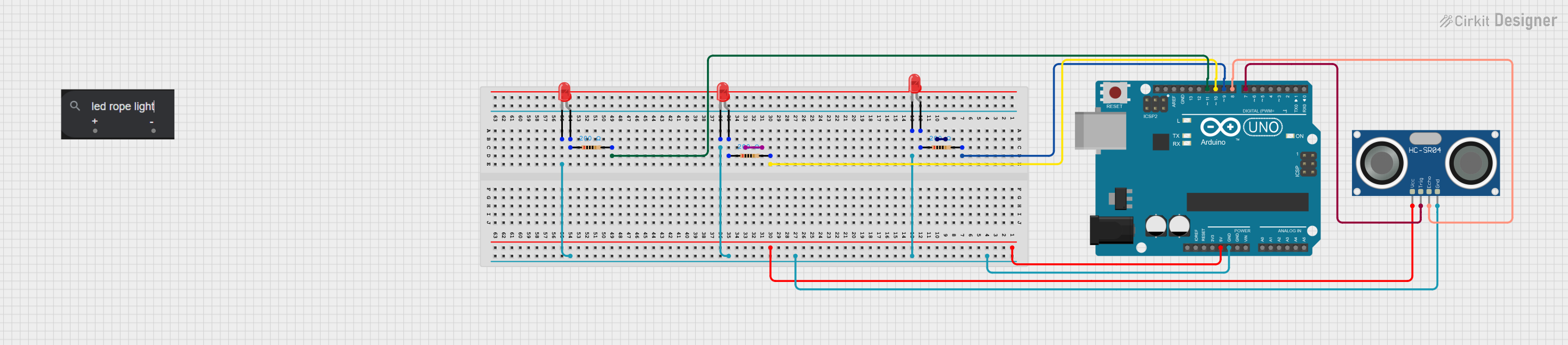
This circuit involves an Arduino UNO microcontroller, an HC-SR04 Ultrasonic Sensor, multiple red LEDs, and resistors. The circuit is designed to interface the ultrasonic sensor with the Arduino and control the LEDs based on the sensor's readings.
Component List
Arduino UNO
- Description: A microcontroller board based on the ATmega328P.
- Pins: UNUSED, IOREF, Reset, 3.3V, 5V, GND, Vin, A0, A1, A2, A3, A4, A5, SCL, SDA, AREF, D13, D12, D11, D10, D9, D8, D7, D6, D5, D4, D3, D2, D1, D0
LED ROPE LIGHT (12V)
- Description: A 12V LED rope light.
- Pins: positive, negative
HC-SR04 Ultrasonic Sensor
- Description: An ultrasonic sensor used for distance measurement.
- Pins: VCC, TRIG, ECHO, GND
LED: Two Pin (red)
- Description: A standard red LED.
- Pins: cathode, anode
Resistor
- Description: A resistor with a resistance of 200 Ohms.
- Pins: pin1, pin2
- Properties: Resistance: 200 Ohms
Wiring Details
Arduino UNO
- D9: Connected to pin2 of a Resistor.
- D10: Connected to pin2 of a Resistor.
- D11: Connected to pin2 of a Resistor.
- 5V: Connected to VCC of the HC-SR04 Ultrasonic Sensor.
- GND: Connected to cathode of multiple LEDs and GND of the HC-SR04 Ultrasonic Sensor.
- D8: Connected to ECHO of the HC-SR04 Ultrasonic Sensor.
- D7: Connected to TRIG of the HC-SR04 Ultrasonic Sensor.
LED ROPE LIGHT (12V)
- positive: Not connected.
- negative: Not connected.
HC-SR04 Ultrasonic Sensor
- VCC: Connected to 5V of the Arduino UNO.
- TRIG: Connected to D7 of the Arduino UNO.
- ECHO: Connected to D8 of the Arduino UNO.
- GND: Connected to GND of the Arduino UNO.
LED: Two Pin (red)
- cathode: Connected to GND of the Arduino UNO.
- anode: Connected to pin1 of a Resistor.
Resistor
- pin1: Connected to anode of a LED.
- pin2: Connected to D9, D10, or D11 of the Arduino UNO.
Documented Code
Arduino UNO Code (sketch.ino)
void setup() {
  // put your setup code here, to run once:

}

void loop() {
  // put your main code here, to run repeatedly:

}
Documentation (documentation.txt)
This documentation provides a comprehensive overview of the circuit, including a summary, detailed component list, wiring details, and the code used in the microcontroller.