
Arduino-Controlled Bluetooth Relay Switch for Bulb and DC Motor
View and Edit Project In Cirkit Designer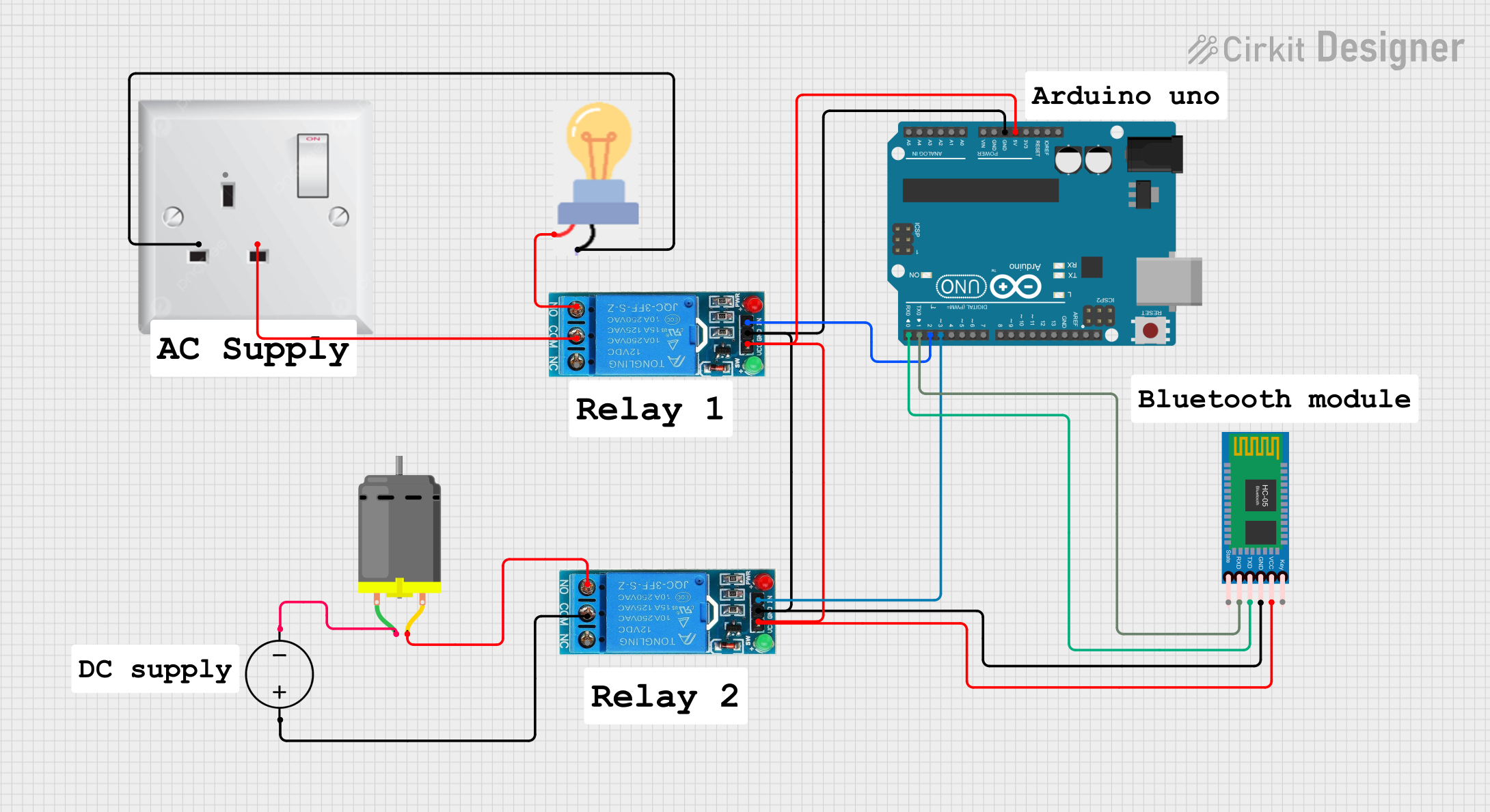
Circuit Documentation
Summary of the Circuit
This circuit is designed to control a bulb and a DC motor using an Arduino UNO microcontroller and two 12V single-channel relays. The HC-05 Bluetooth module is included to provide wireless communication capabilities, potentially for remote control purposes. The Arduino UNO is programmed to interact with the relays, which in turn switch the high-power circuits for the bulb and the DC motor. The power for the circuit is provided by a DC power source and an AC wall plug point.
Component List
HC-05 Bluetooth Module
- Description: A Bluetooth module for wireless communication.
- Pins: Key, VCC, TXD, RXD, State, GND
12V Single Channel Relay (x2)
- Description: Electromechanical switches used to control high power devices.
- Pins: NC (Normally Closed), COM (Common), NO (Normally Open), IN (Input), GND, VCC
Arduino UNO
- Description: A microcontroller board based on the ATmega328P.
- Pins: UNUSED, IOREF, Reset, 3.3V, 5V, GND, Vin, A0-A5, SCL, SDA, AREF, D0-D13
Bulb
- Description: An electric light source.
- Pins: GND, power
DC Power Source
- Description: Provides the DC voltage required for the circuit.
- Pins: Ground, Positive
AC Wall Plug Point
- Description: Provides AC power from a wall outlet.
- Pins: E (Earth), N (Neutral), L (Live)
DC Motor
- Description: An electric motor powered by direct current.
- Pins: pin 1, pin 2
Wiring Details
HC-05 Bluetooth Module
- VCC connected to 5V power supply from Arduino UNO.
- TXD connected to D0 (RX) on Arduino UNO.
- RXD connected to D1 (TX) on Arduino UNO.
- GND connected to common ground.
12V Single Channel Relay (1st Instance)
- VCC connected to 5V power supply from Arduino UNO.
- GND connected to common ground.
- IN connected to D2 on Arduino UNO.
- COM connected to L from AC wall plug point.
- NO connected to power on the bulb.
12V Single Channel Relay (2nd Instance)
- VCC connected to 5V power supply from Arduino UNO.
- GND connected to common ground.
- IN connected to D3 on Arduino UNO.
- COM connected to Positive from DC Power Source.
- NO connected to pin 2 on the DC Motor.
Bulb
- GND connected to N from AC wall plug point.
- Power connected to NO on the 1st relay instance.
DC Motor
- Pin 1 connected to Ground from DC Power Source.
- Pin 2 connected to NO on the 2nd relay instance.
Arduino UNO
- 5V used to supply power to the Bluetooth module and both relays.
- GND used as common ground for the circuit.
- D0 (RX) connected to TXD on HC-05 Bluetooth Module.
- D1 (TX) connected to RXD on HC-05 Bluetooth Module.
- D2 connected to IN on the 1st relay instance.
- D3 connected to IN on the 2nd relay instance.
Documented Code
Arduino UNO Code (sketch.ino)
void setup() {
  // put your setup code here, to run once:

}

void loop() {
  // put your main code here, to run repeatedly:

}
Note: The provided code is a template and does not contain any functional code to control the relays or communicate with the HC-05 Bluetooth module. This will need to be implemented according to the specific requirements of the circuit's intended operation.