
Arduino Nano and L298N Motor Driver Controlled Peltier Module and Water Pump System
View and Edit Project In Cirkit Designer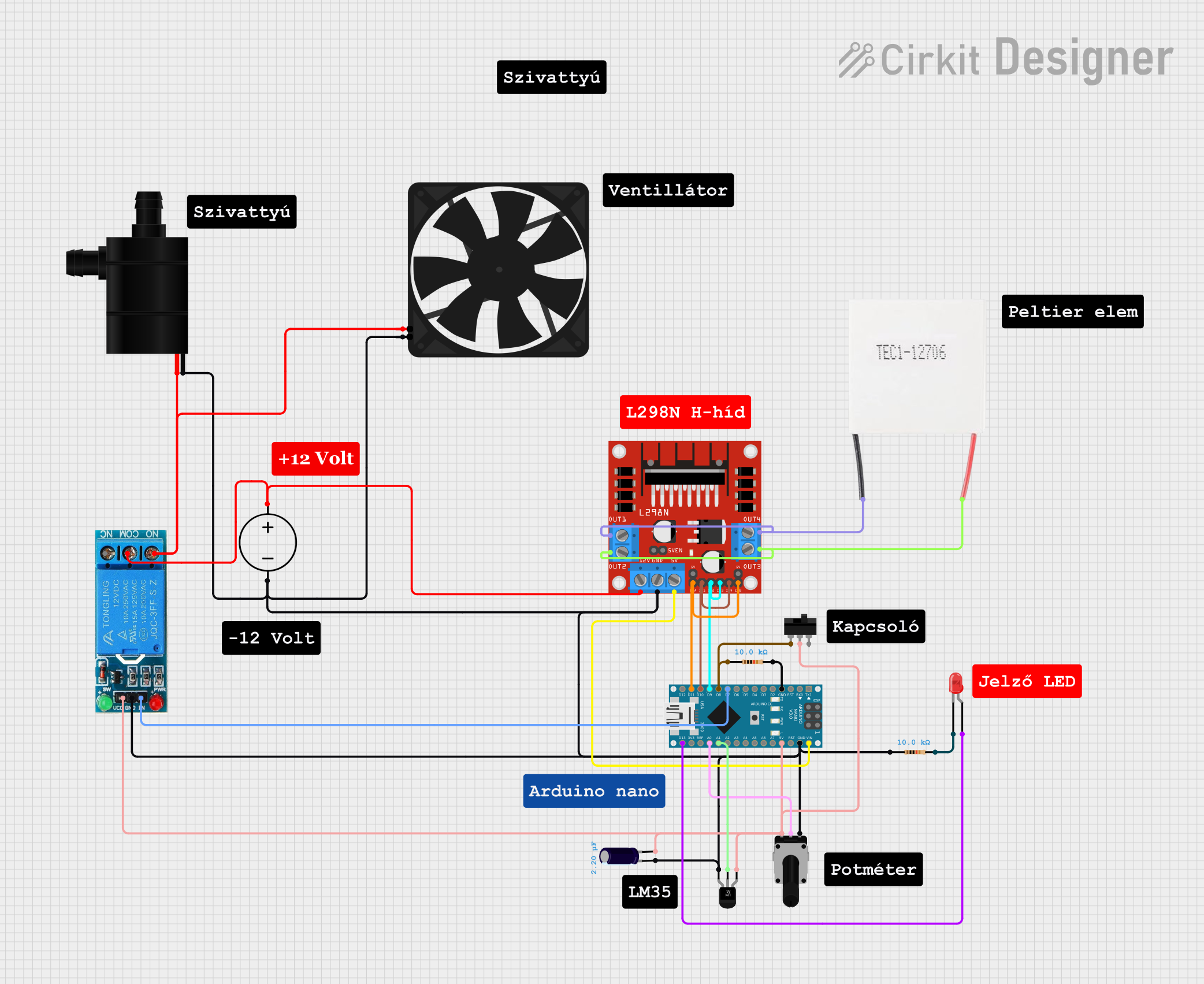
Circuit Documentation
Summary
This document provides a detailed overview of a circuit that includes various components such as an L298N DC motor driver, a Peltier module, a water pump, a fan, a DC power source, an Arduino Nano, a rotary potentiometer, resistors, a toggle switch, an LED, a 12V single-channel relay, a temperature sensor (LM35), and an electrolytic capacitor. The circuit is designed to control and monitor various devices using an Arduino Nano microcontroller.
Component List
L298N DC Motor Driver
- Pins: OUT1, OUT2, 12V, GND, 5V, OUT3, OUT4, 5V-ENA-JMP-I, 5V-ENA-JMP-O, +5V-J1, +5V-J2, ENA, IN1, IN2, IN3, IN4, ENB
- Description: Motor driver for controlling DC motors.
Peltier Module
- Pins: Negative, Positive
- Description: Thermoelectric cooler for heating and cooling applications.
Water Pump
- Pins: VCC, GND
- Description: Pump for circulating water.
Fan
- Pins: GND, 5V
- Description: Cooling fan.
DC Power Source
- Pins: Ground, Positive
- Description: Provides DC power to the circuit.
Arduino Nano
- Pins: D1/TX, D0/RX, RESET, GND, D2, D3, D4, D5, D6, D7, D8, D9, D10, D11/MOSI, D12/MISO, VIN, 5V, A7, A6, A5, A4, A3, A2, A1, A0, AREF, 3V3, D13/SCK
- Description: Microcontroller for controlling the circuit.
Rotary Potentiometer
- Pins: leg1, wiper, leg2
- Description: Variable resistor for adjusting resistance.
- Properties: Resistance: 10,000 Ohms
Resistor
- Pins: pin1, pin2
- Description: Fixed resistor.
- Properties: Resistance: 10,000 Ohms
Toggle Switch
- Pins: L1, COM, L2
- Description: Switch for toggling connections.
LED: Two Pin (red)
- Pins: cathode, anode
- Description: Light-emitting diode.
12V Single Channel Relay
- Pins: NC, COM, NO, IN, GND, VCC
- Description: Relay for switching high-power devices.
Temperature Sensor (LM35)
- Pins: +Vs, Vout, GND
- Description: Sensor for measuring temperature.
Electrolytic Capacitor
- Pins: -, +
- Description: Capacitor for filtering and smoothing.
- Properties: Capacitance: 0.0000022 Farads
Wiring Details
L298N DC Motor Driver
- OUT1 connected to OUT4 and Negative of Peltier Module.
- OUT2 connected to OUT3 and Positive of Peltier Module.
- 12V connected to COM of 12V Single Channel Relay and Positive of DC Power Source.
- GND connected to GND of Water Pump, leg1 of Rotary Potentiometer, - of Electrolytic Capacitor, GND of Temperature Sensor (LM35), GND of Fan, pin1 of Resistor, GND of 12V Single Channel Relay, GND of Arduino Nano, and Ground of DC Power Source.
- 5V connected to VIN of Arduino Nano.
- ENA connected to ENB and D11/MOSI of Arduino Nano.
- IN1 connected to IN4 and D10 of Arduino Nano.
- IN2 connected to IN3 and D9 of Arduino Nano.
Peltier Module
- Negative connected to OUT1 and OUT4 of L298N DC Motor Driver.
- Positive connected to OUT2 and OUT3 of L298N DC Motor Driver.
Water Pump
- GND connected to GND of L298N DC Motor Driver.
- VCC connected to 5V of Fan and NO of 12V Single Channel Relay.
Fan
- GND connected to GND of L298N DC Motor Driver.
- 5V connected to VCC of Water Pump.
DC Power Source
- Ground connected to GND of L298N DC Motor Driver.
- Positive connected to 12V of L298N DC Motor Driver.
Arduino Nano
- VIN connected to 5V of L298N DC Motor Driver.
- GND connected to GND of L298N DC Motor Driver.
- D11/MOSI connected to ENA and ENB of L298N DC Motor Driver.
- D10 connected to IN1 and IN4 of L298N DC Motor Driver.
- D9 connected to IN2 and IN3 of L298N DC Motor Driver.
- D7 connected to IN of 12V Single Channel Relay.
- D8 connected to pin1 of Resistor and L1 of Toggle Switch.
- 5V connected to COM of Toggle Switch, leg2 of Rotary Potentiometer, + of Electrolytic Capacitor, +Vs of Temperature Sensor (LM35), VCC of 12V Single Channel Relay.
- A1 connected to Vout of Temperature Sensor (LM35).
- A0 connected to wiper of Rotary Potentiometer.
- D13/SCK connected to anode of LED.
Rotary Potentiometer
- leg1 connected to GND of L298N DC Motor Driver.
- wiper connected to A0 of Arduino Nano.
- leg2 connected to COM of Toggle Switch.
Resistor
- pin1 connected to L1 of Toggle Switch.
- pin2 connected to GND of Arduino Nano.
Toggle Switch
- L1 connected to pin1 of Resistor.
- COM connected to leg2 of Rotary Potentiometer.
- L2 not connected.
LED: Two Pin (red)
- anode connected to D13/SCK of Arduino Nano.
- cathode connected to pin2 of Resistor.
12V Single Channel Relay
- NC not connected.
- COM connected to 12V of L298N DC Motor Driver.
- NO connected to VCC of Water Pump and 5V of Fan.
- IN connected to D7 of Arduino Nano.
- GND connected to GND of L298N DC Motor Driver.
- VCC connected to 5V of Arduino Nano.
Temperature Sensor (LM35)
- +Vs connected to 5V of Arduino Nano.
- Vout connected to A1 of Arduino Nano.
- GND connected to GND of L298N DC Motor Driver.
Electrolytic Capacitor
- - connected to GND of L298N DC Motor Driver.
- + connected to COM of Toggle Switch.
Documented Code
Arduino Nano Code (sketch.ino)
void setup() {
  // put your setup code here, to run once:

}

void loop() {
  // put your main code here, to run repeatedly:

}
Additional Documentation (documentation.txt)
This document provides a comprehensive overview of the circuit, including a summary, component list, wiring details, and documented code. Each component is described, and its connections are detailed to ensure proper assembly and functionality of the circuit.