Cirkit Designer
Your all-in-one circuit design IDE
Home /
Project Documentation
Solar-Powered Water Pump with Battery Backup and Manual Control

Circuit Documentation
Summary of the Circuit
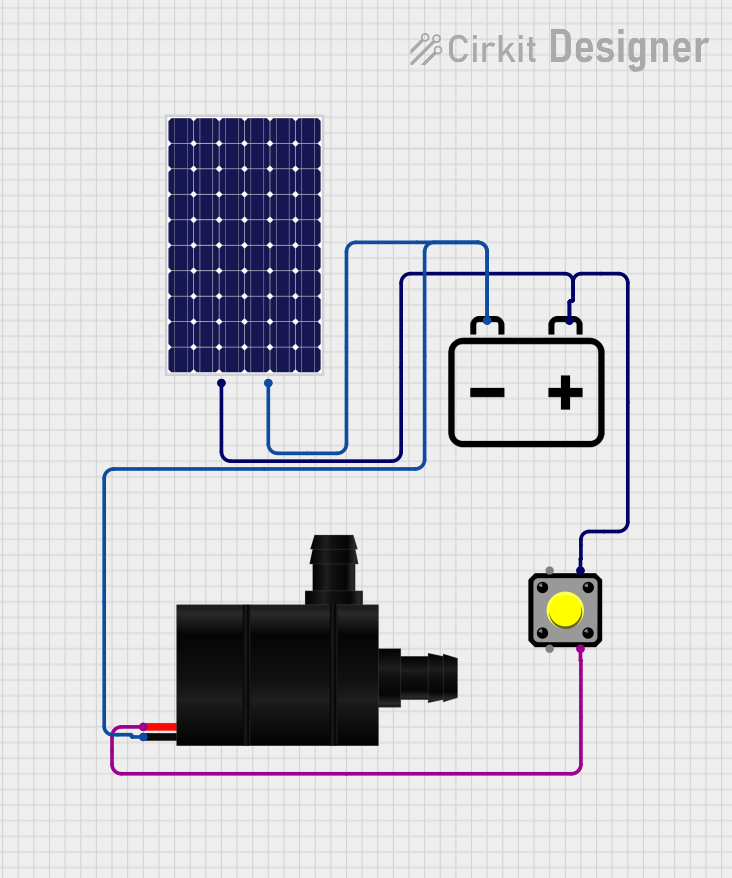
This circuit appears to be a simple solar-powered system designed to drive a water pump. The system uses a solar panel to charge a 12v battery, which in turn can provide power to the water pump. A pushbutton is included in the circuit, likely to control the activation of the water pump. The solar panel and the battery are connected in parallel, providing a stable voltage source for the pump. The pushbutton acts as a switch to control the power flow from the battery to the water pump.
Component List
Solar Panel
- Description: A photovoltaic panel that converts sunlight into electrical energy.
- Pins:
+(Positive),-(Negative)
Water Pump
- Description: An electromechanical device that moves water by mechanical action, typically powered by electricity.
- Pins:
VCC(Power Supply),GND(Ground)
Pushbutton
- Description: A simple switch mechanism for controlling some aspect of a machine or a process.
- Pins:
Pin 2,Pin 1,Pin 3,Pin 4
12v Battery
- Description: An energy storage device that provides electrical power to the circuit.
- Pins:
+(Positive),-(Negative)
Wiring Details
Solar Panel
- Positive Pin (
+): Connected to the positive pin of the 12v Battery and Pin 4 of the Pushbutton. - Negative Pin (
-): Connected to the negative pin of the 12v Battery and the GND pin of the Water Pump.
Water Pump
- VCC (Power Supply): Connected to Pin 3 of the Pushbutton.
- GND (Ground): Connected to the negative pin of the Solar Panel and the 12v Battery.
Pushbutton
- Pin 4: Connected to the positive pin of the Solar Panel.
- Pin 3: Connected to the VCC pin of the Water Pump.
12v Battery
- Positive Pin (
+): Connected to the positive pin of the Solar Panel and Pin 4 of the Pushbutton. - Negative Pin (
-): Connected to the negative pin of the Solar Panel and the GND pin of the Water Pump.
Documented Code
There is no embedded code provided for any microcontrollers in this circuit. If the circuit is later updated to include a microcontroller for automated control or monitoring, the code will be documented in this section.